Building instruments that boldly go into some of the solar system’s most extreme environments presents unique challenges for instrument designers. Keith Cooper explores how they do it

Space is not a friendly place for instruments to operate. Cosmic radiation fries their electronics; they have to cope with extreme variations in temperature; and for missions venturing close to the Sun, the solar wind can gradually erode their exposed optical surfaces. Consider Solar Orbiter, a European Space Agency mission designed to observe the Sun from relatively close quarters. The spacecraft’s elliptical orbit will periodically take it to within 42 million kilometres of the Sun, where it will reach temperatures as high as 790 K. A sunshield will provide some protection, but Solar Orbiter’s 10 instruments – including an ultraviolet spectrometer called SPICE (Spectral Imaging of the Coronal Environment) – will still have to cope with intense heat. Furthermore, several of these instruments need to be actively chilled to as low as 213 K.
Some planetary environments are even harsher. Venus, for example, has a surface temperature of 730 K, a surface pressure nearly 90 times higher than Earth’s, and a corroding, acidic atmosphere. Only a handful of spacecraft have ever successfully landed there, and those that did survived only a few hours inside bulky pressure vessels before succumbing to the unforgiving conditions. If we want to send spacecraft there again, we will need to find alternative solutions.
The combination of several different extreme conditions poses tough challenges for instrument designers. However, careful planning, design and testing can minimize the hazards, while ingenious modelling can help scientists and engineers identify potential problems early. For example, one of the most important tasks at the beginning of Solar Orbiter’s design phase was to develop a thermal model of the spacecraft. This model indicates which parts of the spacecraft become hottest, which parts remain coolest and which areas can safely be used to shed heat. The thermal models for each of the instruments on a spacecraft must complement all of the others, as well as the craft’s overall thermal profile. Care has to be taken to ensure that one instrument does not shed excess light and heat in a way that warms its neighbours. Only when this is achieved is it possible to begin building the instruments. “It’s a high-risk business, so you have to show feasibility right from the start,” says Martin Caldwell, an instrument designer at the UK’s Science and Technology Facilities Council’s RAL Space, where SPICE was built and tested. “No instruments get designed or built without knowing they are going to survive.”
Hiding from the heat – or not
Several techniques exist to boost instruments’ chances of surviving harsh environments. Most of the instruments on Solar Orbiter, for example, sit behind a 3.1 × 2.4 m sunshield built from multiple layers of insulation foil sandwiched between two black-plated surfaces. The instruments can’t hide from the sunlight entirely, of course, because they need to make observations, so the shield contains small doors leading to feedthroughs that allow sunlight into the instruments. Because the shield itself can expand with heat, these doors are deliberately oversized so that lines of sight to instruments are not blocked.
SPICE is designed to allow 30 W of sunlight to enter via its feedthrough. Light then strikes its main mirror coated with boron carbide, which reflects ultraviolet frequencies onto the instrument’s diffraction grating and then onto its detectors. Visible and infrared frequencies, which carry much of the heat, pass straight through the mirror and back out into space. In this way, the mirror and its exit path to space help to cool the instrument “passively”, as opposed to “active” cooling, which is typically provided by louvers or radiators filled with liquid helium. “It’s amazing how, with just passive cooling, you can get very different temperatures around a spacecraft,” says Caldwell.
What happens when there is no way of hiding from the heat, like on Venus? The short lifespan of previous landers has helped dissuade space agencies from sending more such craft to its surface, but that could be about to change. Scientists working at NASA’s Glenn Research Center have developed new circuitry that could potentially survive for months, if not years. Electronics built from the semiconductor silicon carbide (SiC) have been in use on high-power devices for some time now and are well known for operating at high temperatures. However, says Philip Neudeck of the Glenn Research Center, what most people consider “high temperature” is only around 400 K to 520 K – still a far cry from Venusian conditions”. “There have been much briefer prototype demonstrations of silicon-carbide electronics at Venusian temperatures, but what hadn’t been demonstrated, until our recent work at NASA, is their long-term durability, especially within Venus’ atmospheric chemistry,” he explains.
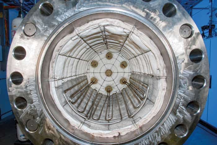
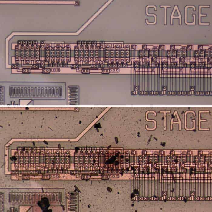
Neudeck’s team has shown that SiC electronics have what it takes to survive on Venus. After building a test model with an integrated circuit chip containing just 24 transistors, Neudeck’s group used the Glenn Extreme Environments Rig (GEER) to simulate Venusian conditions and put the SiC electronics through their paces. This 1.2 m long stainless-steel chamber has a volume of 800 litres and can simulate not only the pressure and temperature on Venus, but also the 10 most abundant chemical constituents of the planet’s corrosive atmosphere with an accuracy down to mere parts per million. The rig can also be adapted for other environments, including those in the atmospheres of Jupiter and Saturn, and it can achieve even higher pressures than those found on Venus, albeit at lower temperatures. In a way, it’s the reverse of a vacuum chamber.
“It’s no small feat to replicate those conditions on Earth, especially inside a chamber this size,” Neudeck says. His group had access to the GEER chamber for a straight run of 21 days and at the end the SiC electronics were still operating at full capacity. In comparison, the current record survival time on Venus is a mere two hours and seven minutes, achieved by the Soviet Union’s Venera 13 probe in 1982. The ultimate aim, Neudeck says, is to develop more complex electronics that can function indefinitely.
Thermal vacuum testing
At RAL Space, testing is also carried out in vacuum chambers built on a similar scale to the GEER. The chambers at its facility in Oxfordshire range from 0.5 m in diameter to a 5 m diameter chamber recently built by the Dutch company Schelde Exotech and designed specifically for instrument calibration testing. A second 5 m diameter, 6 m long chamber is being manufactured by the Spanish firm Cadinox, which won the tender from Added Value Solutions, a Spanish firm that has offices near RAL Space. Several even larger vacuum chambers, up to 8 m in diameter, are also being considered for the future, according to Giles Case, manager of the assembly, integration and verification facility at RAL Space.
Such large vacuum chambers are “pretty bespoke”, Case says. The specifications for chambers intended for spacecraft and instrumentation testing can vary, he explains, but in general they are constructed from electro-polished stainless steel that reduces outgassing. Beyond that, individual specifications may include how much weight it can carry, how many instruments can be adorned within it and how many doors and viewing points it has. A 5 m vacuum chamber costs around £10m, Case says, and the high cost is one reason why there are only around 10 large facilities for testing spacecraft and their instruments in Europe. By expanding their vacuum–chamber capability, he argues that RAL Space will help enable the UK to “access the wider space market”.
Final testing in a vacuum chamber can take weeks, as it did for SPICE in March and April 2017. Once inside the chamber, SPICE was mounted on a platform that acts as a temperature interface, controlled by a black-painted thermal shroud that surrounds the instrument under testing. In addition to a bright lamp to simulate sunlight, the temperature interface mimics the operating temperatures that SPICE will experience in space. This set-up is capable of producing temperatures as low as 93 K or as high as 373 K. SPICE was tested at 350 K – 20 degrees higher than its intended op-erating temperature.
Setting an instrument up inside a vacuum chamber is complicated, so to save time and effort, Caldwell explains that thermal tests are generally conducted alongside other performance trials. For SPICE, those tests include an ultraviolet test with a narrowband lamp to ensure the instrument was correctly calibrated and focused (some of SPICE’s ultraviolet testing had previously also taken place at the Metrology Light Source in Germany). There’s also a shake test and a long bake-out to clean the instrument. The vacuum chamber itself had to be extremely clean because even the smallest amount of organic molecules sticking to the optics could cause darkening when exposed to ultraviolet light. To that end, the instrument had to undergo constant gas purges to keep the optics clear of contamination.
When the testing is finished, an instrument typically remains in the chamber while the observing ESA specialists analyse the results. “Very often they might want extra measurements,” Caldwell says. “So it makes sense to keep it in there until we’re ready for delivery.” After a month inside the chamber, SPICE was delivered to Airbus in Stevenage where, on 21 May 2017, it was mated to Solar Orbiter’s spacecraft structure – the culmination of five years’ worth of development at RAL Space. Once the other instruments are added, the entire spacecraft will undergo final thermal testing inside a vacuum chamber to compare with the previous testing performed on the earlier thermal model. If all of the results check out correctly, the orbiter will blast off from Earth and head towards the Sun in October 2018.
Revise and adapt
Neudeck also has big plans for 2018. By then he hopes to be testing heat-tolerant SiC electronics that have 10 times more transistors than the first prototype, which is roughly the same electronic complexity as the integrated circuits aboard early solar-system missions such as the Pioneer and Viking probes. However, that doesn’t necessarily mean a new Venus mission is on the horizon. Echoing Martin Caldwell’s warning that space is a high-risk business, Neudeck emphasizes the need to minimize that risk by subjecting the instrumentation to considerable scrutiny. “We first have to critically evaluate, improve and understand the technology, and be able to produce and qualify it in sufficiently large testing volumes, before we can actually fly it,” he says. “But there’s no doubt we are laying the path.”
Commercial interests could help accelerate development in this area. Aerospace companies are interested in using Neudeck’s technologies for sensors that sit inside the hot areas of jet engines to monitor and control the rate at which fuel is burnt. Additional interest comes from the energy and automotive industries. “We’re looking to leverage these commercial interests to get these electronics to Venus faster,” says Neudeck.
SiC electronics could potentially also find other space-based uses. In addition to coping with very high temperatures and pressures, the electronics should also theoretically exhibit some resistance to radiation, although tests still need to be conducted to prove and quantify the radiation advantage. If it can be proven, though, then it could ultimately make it possible for spacecraft to explore the environment around Jupiter’s harsh radiation belts. As recently as October 2016, NASA’s Juno probe suffered a glitch as radiation damaged its onboard electronics, causing it to miss an opportunity to take data during a close fly-by of Jupiter. SiC electronics might not only let spacecraft survive around the giant planet, but also permit deeper ventures into its atmosphere.
When it comes to high-risk environments in space, borrowing from what has come before can sometimes be the safer option. “One of the things that made Solar Orbiter possible was learning from the BepiColombo spacecraft,” Caldwell says, referring to ESA’s upcoming Mercury mission, which will also launch in 2018, but which has been in development for longer than Solar Orbiter. “In the space business, everybody is desperate to rely on things that have been done before, that are available and safe to use,” he adds. However, as the SiC electronics show, sometimes the old technology simply isn’t good enough. In those cases, instrument designers must start again, and reinvent a better, tougher wheel.
- Enjoy the rest of the 2017 Physics World Focus on Vacuum and Instruments in our digital magazine or via the Physics World app for any iOS or Android smartphone or tablet.