From Hollywood blockbusters to the design of aircraft cockpits, the visual-effects industry relies on tracing the path of light to create scenes that do not and may never exist
From the dawn of history people have tried to convey to others an impression of the mental images they see in their mind’s eye. We have come a long way since the Renaissance times of Albrecht Dürer and his attempts to use Euclid’s mathematical methods as a basis for painting. Today, movie directors want to make us believe that worlds that never were and never will be are as real as our living room. One is well advised to remember, however, that “movie physics” is an approximation of reality, and that it may differ substantially from the real world if artistic vision or viewing conventions demand it.
Before we can understand the physics behind visual effects, we have to ask ourselves a fundamental question: what is colour? There is no such thing as colour in nature, or as Newton said, “rays, properly expressed, are not coloured”. The intensity of the electromagnetic radiation emitted by a source varies as a function of both frequency and direction. A material object will react to the radiation emitted by another object by altering both its frequency distribution and its direction. Finally some of the radiation may reach our eyes.
In a simplified model we can say that our eye contains three kinds of sensors (called cones) that react differently to radiation of different frequencies. Our brain translates these stimuli into colour impressions. These three sensors are the main reason why it is sufficient for us to represent most electromagnetic spectra of interest – spectra in the visible domain – as a linear superposition of three base spectra. In televisions, for example, red, green and blue are typically used for these purposes.
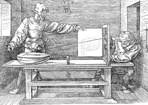
Creating a 2D image of a 3D scene on a computer – a process known as rendering – is still quite demanding in terms of processing power and memory resources. Hence practically all of the software in this field uses geometric optics, which means that the wave nature of light is ignored. Indeed, this method is essentially the same as the projective approach developed by Dürer in 1525 (figure 1). Light spectra are represented as a linear superposition of three components, which we shall sloppily call “colour”.
All in the mind
To render an image, the scene must first be generated inside the computer. In other words, the geometric objects comprising the scene must be constructed. Several highly sophisticated commercial programs are available for this purpose, such as 3D Studio Max from Autodesk, Maya from Alias, and XSI from Softimage. These programs describe the geometry of a scene in mathematical terms with the help of polynomials, rational functions or just simple triangles in a manner that is transparent to the user. They are also used to control the time evolution of a scene by predetermining the position of a geometric object within each computer-generated frame of film.
Movies are displayed at a rate of 24 frames per second, which means there are about 130,000 frames in a typical 90 minute film. Even if we only spend 10 minutes rendering one frame, then about three years of computer time is needed to make one movie. Until recently this meant that most computer-generated scenes only involved the visible surfaces of objects. Today, however, increased computing power allows us to achieve far better animations by modelling the underlying structure of objects too.
This is especially effective for creature animations, such as in the movie Incredible Hulk, in which bones can be positioned relative to one another by placing constraints on their possible movements. Muscles are then attached to the bones like building an anatomical model, albeit usually much simplified. As a result, the muscles will bulge in the right place when an arm is bent, and consequently the skin will stretch and the surface will automatically have the right shape. But there is another important step to be made before a convincing animation is generated.
A modelled creature is not aware of its surroundings, so even a simple task such as placing a foot on a floor requires special software to detect when the foot touches the floor, not to mention the fact that the foot needs to deform under the pressure. This branch of computer modelling is called collision detection, and it contains more sophisticated classical mechanics than we are able to cover here. Instead, we will concentrate on the interaction of light with matter, because this is what makes computer-generated images appear more realistic.
The power of light
The principal quantity of interest when rendering a 3D scene into a 2D image is the radiance. This is the power of the light that is emitted per projected surface area into a given solid angle, and it is measured in watts per square metre per steradian. Crucially, radiance is conserved, which means that the radiance leaving a surface in a certain direction and travelling through a vacuum will arrive at another surface lying in this direction without loss. If there is no radiance arriving at our eyes we will not see anything, so we need to include objects such as the Sun or a light bulb to generate it. Abstractly, these objects are called light sources.
To render colour images we actually look at each of the three frequency channels independently. We register the spectral radiance of each channel that arrives at our virtual camera and then convert their combined effect into the appropriate colour for each pixel in the camera. However, simply registering the radiance that arrives directly from a light source would not result in very interesting pictures because this radiance provides no information about the rest of the objects in the scene. The next challenge is therefore to simulate the response of objects that are not sources of light to the radiance arriving at them.
Conservation of energy requires that the total radiance leaving a material may not be more than the total radiance arriving. Part of this radiance may be absorbed and converted to heat, while the rest is either reflected or transmitted. In computer graphics, reflection and transmission are described by so-called bi-directional distribution functions.
The idea behind the bi-directional reflection distribution function (BRDF) is quite straightforward: it tells us what fraction of the radiance arriving at a point on the surface from a given direction will leave in another direction after being reflected. A general BRDF is therefore described by seven parameters: three for the position in space and two for each of the incoming and outgoing directions. Dealing with such multidimensional functions requires extensive computer resources. Luckily, however, the BRDF of many materials may be approximated by a combination of several simple BRDFs. Two of the simplest of these are specular and diffuse reflection.
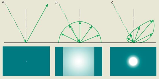
In specular reflection the surface of a material behaves like an ideal mirror, and the outgoing radiance is the mirror image of the incoming radiance (figure 2). In diffuse reflection, on the other hand, the direction of the outgoing radiance is independent of the incoming direction, which means that the light is equally reflected in all directions. Glossy reflections are somewhere in between these two extremes. In bi-directional transmission distribution functions (BTDF) it is also necessary to include refraction, which is described by Snell’s law.
The rendering equation
In 1986 James Kajiya, then at the California Institute of Technology, formulated the fundamental problem in computer graphics in terms of a transport equation called the rendering equation: the radiance, L, arriving at any point is the radiance directly arriving from all visible light sources, S, plus the total radiance arriving from all visible surfaces via reflection or transmission. Hence we end up with an equation, L = S + (BRDF + BTDF)L, that describes the transport of radiance from the light sources through the scene to the camera plane. The big problem is that the unknown function L appears on both sides of the equation.
This kind of equation may be tackled using a simple but hugely successful approach known to physicists as the Born series. Just replace L on the right-hand side of the equation by S + (BRDF + BTDF)L, and repeat this substitution process as often as is needed. In the case of plain numbers, rather than functions, the Born series becomes especially simple. If we take the equation x = 1 + qx, for example, and substitute x in the right-hand side by 1 + qx, we are left with the expression x = 1 + q(1 + qx). By repeating this procedure we can obtain x = 1 + q + q2 + q3 + …. However, we may also solve the original equation directly to give x = 1/(1 – q), and thus we are able to derive the well known formula for the geometric series: 1/(1 – q) = 1 + q + q2 + q3 + ….
Unfortunately, L is a function rather than a number, and this means that we cannot, in general, solve the transport equation directly. Instead we need to approximate the solution by stopping the series expansion after a finite number of substitutions, and set L to zero in the last substitution. The resulting finite series describes the path that the radiance takes through the scene by interacting with the materials associated with the geometric objects placed in it. A trivial approximation would be L = S: in this case the image only includes the radiance of the light sources that arrives directly at the camera. The next approximation that we can introduce, L = S + (BRDF + BTDF)S, contains more information about the scene because it also includes radiance that has interacted once with other objects in the scene.
From the viewpoint of the camera, we notice that we only register objects that are directly visible from the camera and that are illuminated by a light source. In other words, this is the projective method used by Dürer. The next iteration would be L = S + (BRDF + BTDF)S + (BRDF + BTDF)2S, which takes into account at most two interactions of the light with other objects, such as a reflection in a mirror. To then illuminate the reflected object we would need a further iteration, and so on. By including more terms in the Born series we may take into account as many light-object interactions as we need to produce a realistic-looking image.
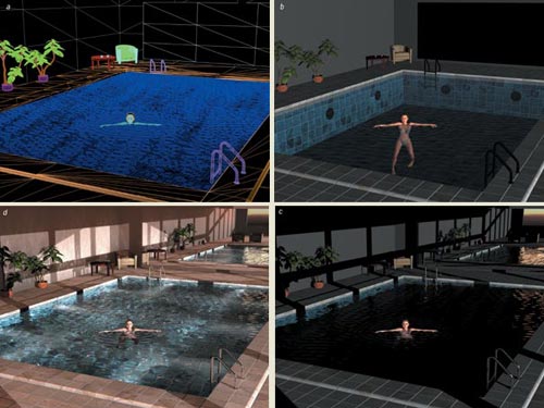
Not only is the simplest Born-series method equivalent to Dürer’s projection technique, it is also the method used by today’s graphics hardware boards. Many of Pixar’s movies, such as Toy Story, were generated using this method (which is also known as scanline rendering) using its own rendering program Renderman. The intrinsic limitation of plain scanline rendering, however, is that there are no reflections or refractions. The result can be seen in figure 3b, for example, where the mirror on the right wall and the chrome surface of the pool ladders appear black. To obtain the effects of reflection with a scanline renderer we have to use some tricks. The pool scene, for example, can be rendered first from the viewpoint of a camera placed at the mirror position, with the mirror replaced by a window. The resulting image may then be used to replace the black mirror surface. However, this approach would be much more difficult for non-planar surfaces, such as the pool ladders.
A similar method is used to calculate shadows. For each light source the scene is rendered with a camera placed at the position of the light. However, instead of recording the colour, it is only necessary to remember the distance of any geometric object from the camera. This “shadow map” image may later be used to determine whether an object casts a shadow on another object during the rendering process. The scanline-rendering image also appears quite dark, which is usually remedied by placing some constant “background light” everywhere in the scene. In addition, lights that defy the law of energy conservation can be used: these lights do not follow the usual inverse square law and make everything in the scene appear brighter.
To enhance an image, computer-generated images or real photographs can be incorporated: all the swimming pool tiles in figure 3d, for example, were produced using this method. This approach is exactly opposite to the “blue screen” approach in which actors are filmed in front of a background that has a specific colour after which all the pixels that have this colour are replaced by pixels from computer-generated scenes. This is the standard method used to blend actors and portions of real scenery into a computer-generated background, as was done for the Colosseum Maximus scenes in the film Gladiator.
Ray tracing
There is a big difference, however, between rendering an image and the visual effects that you ultimately see in the cinema. I work for a company called mental images in Berlin, which was established in 1986 to create photorealistic computer-generated graphics. Currently our scientific staff consists of about 25 people, who are either computer scientists, physicists or mathematicians. Our rendering software “mental ray” differs from Renderman’s scanline approach because it uses a technique known as ray tracing.
Renderman and mental ray have one thing in common: they provide the infrastructure for describing how materials interact with light. But each production house, such as Dreamworks, Pixar or Sony, has special needs that depend on its current projects. Renderman provides a specialized “shading language” for this purpose, while mental ray allows custom functions written in the C programming language to be used. In other words, visual-effects companies develop shaders that are geared towards their specific needs, while rendering software like mental ray provides the “physics glue” that steers light rays through the scene and enables the shaders to interact.
Ray tracing was introduced to computer graphics by Arthur Appel in 1968, then working for IBM at their laboratory in Yorktown Heights, although the principle was allegedly first used some centuries earlier by Descartes in his attempts to explain how rainbows are generated. Ray tracing goes beyond scanline rendering by using more terms of the Born series. However, if we were to follow the radiance emitted by a light source through a scene until it reaches the camera plane, we would waste a lot of effort because only a very small portion of the light will end up at the camera; most of it will end up somewhere else in the scene. It is much better to start at the end: to shoot rays from the focal point of the camera through the pixels comprising the camera plane and out into the scene. This is possible thanks to what is known as the Helmholtz reciprocity principle, which states that the physics remains unchanged if the direction of light in a BRDF or BTDF is reversed.
We then follow these rays through the scene, which means that we have to be able to calculate where the rays intersect various objects. In general this is not possible exactly because there are only a few shapes for which we can calculate their intersection with a ray sufficiently quickly. In mental ray we restrict ourselves to triangles, so all geometric objects are approximated as collections of triangles (figure 3a). These triangles can have different material properties, and these properties determine what happens to the ray when it intersects a particular triangle.
For example the ray may be reflected or refracted, after which it continues its journey through the scene. Computationally, this means that a higher-order term in the Born series will contribute and that each refraction or reflection will increase the order of the contributing term by one. If, on the other hand, the material of the intersected triangle is diffuse, then we have no idea which of the many possible directions the ongoing ray will choose. Hence we stop and just compute the radiance arriving from all light sources. This means that only the current term of the Born series will contribute.
To calculate this contribution we send a special ray called a shadow ray from each light source to the intersection point. If this shadow ray hits another object before it reaches the original triangle, then we know that a shadow will be cast onto this triangle. Otherwise we can transfer the incident radiance back towards the camera, thus giving information about the colour of the pixel in the camera plane.
An image produced with this ray-tracing approach can be seen in figure 3c. The reflections in the mirror and on the pool ladders are now clearly visible, and we can even see a reflection of the bright sky in the mirror reflection of the left-wall window. There are also reflections of the table and the plants on the water surface. However, the water surface for the most part still looks quite unnatural. The reason for this lies in the way we treat shadow rays. Light falling on the water surface is either reflected or refracted towards the pool floor. However, water has a higher refractive index than air, which means that the straight shadow ray will hit the pool or room wall before the light ray when it is shot from the source to the pool floor. The floor of the pool is therefore considered to lie in the shadow, and the water surface appears dark. Ideally we would like to refract the shadow ray too, but mathematically this is a much more difficult problem to solve.
Tracing rays from the light source to the camera is computationally expensive. But it is possible to get round this by tracing rays from the light source through the scene and keeping a record of where these rays hit an object. This is like a bubble chamber in particle physics: it is very difficult to see the actual particles, but it is comparatively easy to see the tracks of the bubbles that they cause as they pass through the chamber. In mental ray we call these rays “photons” because they behave like real photons in many ways, but they should not be mistaken for the real thing. The record of the interactions between these photons and objects in the scene is called the “photon map”.
When our swimming pool is rendered with global illumination, light from everywhere on the sky hemisphere will try to reach it, although most of the light will be stopped by the surrounding building (figure 3d). The photons that enter through the windows reach the pool floor and light it up, which makes the water appear more natural. The principal difference between these photons – which have their trace history stored in the photon map – and the shadow rays is that the former may be refracted, while the latter must follow a straight line.
The colour of the walls, including the shadows on them, shift slightly due to the influence of the colour of the floor tiles. This effect is called “colour bleeding” because the colour of one diffuse surface is affected by another diffuse surface. Another spectacular effect is the appearance of “caustics” in the water and on the rear wall, which are the result of photons that have been specularly reflected or refracted from the undulating water surface.
The perfect image
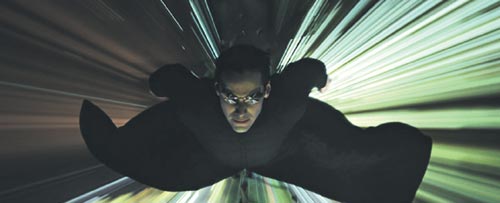
In the last few years computer graphics has taken great strides towards the perfect image. It is becoming increasingly difficult to distinguish photographs from computer-generated images. Mental ray has been used extensively in recent Hollywood films, such as the Matrix movies and Terminator 3. In Matrix Reloaded there are several scenes where even the actors have been digitally recreated, and it is very difficult to distinguish these from the originals. The simulation of clothing and hair is now so sophisticated that there is little room for improvement, and the quality of simulated skin has also increased tremendously.
However, there are still some things current software does not do, or at least does not do well. For example the frequency-dependent refractions that are needed to generate rainbows are still extremely computer intensive, and any effects that depend on the wave nature of light are also beyond current capabilities. Modern computer-graphics software cannot, for instance, reproduce the interference pattern observed in the classic double-slit experiment.
It should also be pointed out that the quest for physically accurate image generation is driven more by design engineering and architecture applications than by the entertainment industry. For the latter it is much more important that images look good, even at the cost of physical accuracy. However, the designers of aircraft cockpits, for example, need to know if there might be problems with the readability of instruments under various lighting conditions. These areas of special visual effects pose entirely new challenges. The plans for an aircraft involve huge databases that need to be accessed by many engineers in many different places all over the world. There is therefore a need to provide those local engineers or customers with high-quality images generated from the most current, centralized databases.
Manufacturers also consider the data underlying the images confidential, although they have no problem letting people access the final images. Hence they are very reluctant to make such data available on CD-ROM (even if the logistical problems of ensuring that everyone is working with the latest CD-ROM could be overcome). Operating from a centralized database then becomes a question of improved access and version control. This is in stark contrast to the movie and entertainment industry, where the image itself is the product that needs to be protected. At mental images we have now started to provide such an infrastructure – called RealityServer – which is beginning to make centralized rendering and multipoint interaction with high-quality images a possibility.
A sound future
As we have seen, today’s commercial rendering software uses geometric optics and only three colour channels, but computers are now fast enough to start looking at the entire visible spectrum. This would allow us to simulate materials that have wavelength-dependent coefficients of reflection or refraction, such as glass prisms. There is also room for improvement in the simulation of people. In the Matrix movies, for example, the skin on the faces of the virtual actors was obtained from processed photographs of the real actors. Researchers are currently trying to avoid this kind of expensive circumnavigation by using better, yet still reasonably simple, mathematical models for the reaction of skin to light.
From a physics point of view we would also like to leave geometric optics behind and use the wave nature of light rays instead. As well as allowing us to simulate the visual effects of interference, this opens up the possibility of simulating sound waves in complex geometries. Architects, for example, might eventually be able to use such software to optimize noise pollution in their buildings.
