Bendy wires generate AC power

You could soon be charging your mobile phone using your shoe thanks to researchers in the US who have created a tiny device that generates electric power as it is stretched and then released.

The device, based on a zinc-oxide wire, can create an alternating current of about 8 pA and a voltage of about 50 mV, which is at least 15 times greater than other tiny generators. The team claims that the process is efficient enough to be used to power remote sensors or even electronic equipment.

The new technology has been developed by Zhong Lin Wang and colleagues at the Georgia Institute of Technology and researchers at the University of Dayton. Earlier this year, Wang unveiled a zinc-oxide nanowire fabric that, when stretched or crumpled, could generate enough electricity to charge a mobile phone.

Their design relied on harvesting the piezoelectricity created by millions of tiny wires that were bent as they gnashed together within the fabric. However, in practice such fabrics would not last long because the gnashing would quickly damage the wires — and it is very difficult to make the fabric such that the wires gnash together properly in the first place.

Improved design

Now, Wang claims to have improved on his design by focusing on the electricity that is generated when individual wires are stretched and released (Nature Nanotechnology DOI:10.1038/NNANO.2008.314).

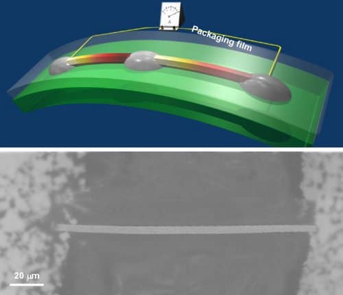
Wang’s team made the new generator by bonding a single zinc-oxide wire — 4 µm thick and 200 µm long — onto a flexible insulating film made of polyimide. The wire is stretched by simply bending the film. The resulting voltage — caused by the piezoelectric effect — is measured by completing the circuit using an ammeter.

To make an AC generator, the team connected one end of the wire to a “Schottky barrier” — a semiconductor device that allows current to flow in one direction through the wire, but not the other. When the wire is stretched, a voltage builds up across the wire, then when the wire is allowed to relax, a similar but opposite voltage appears across the wire.

Connecting in series

Wang told physicsworld.com that an AC voltage of about 50 mV is generated when the wire is stretched by about 0.1% and then released at a rate of 22 cycles per minute by a motor-driven mechanical arm. The team also connected two such wires in series and found that the two output voltages added together when the wires were bent simultaneously — suggesting that a number of generators could be connected together to create higher voltages.

The team also found that increasing the rate at which a wire is strained boosts both the output voltage and current.

The device converts mechanical energy to electrical energy with an efficiency as high as 6.8%. While this is less one tenth the efficiency of a hydroelectric turbine, for example, Wang believes that it is good enough for practical applications because many wires can be integrated together to boost both the power and voltage output.

He also says that his team are investigating how the shape of the wires and the materials used can be modified to maximize efficiency. “I have 15 people working on various parts of this technology,” said Wang, who has filed several patents on using zinc-oxide wires for generating electricity.

Wang believes that the wires could be used to power medical sensors, for example, by implanting them into muscle tissue. They could also be fitted into shoe pads, where they would generate power while the wearer is walking — something that could prove invaluable to soldiers on long missions, who currently have to carry large supplies of batteries.

Invisibility extends out of its shell

Step inside and, at least at a certain wavelength, light would flow smoothly around you as though you were hardly there — that was the thinking behind the world’s first “invisibility cloak”, which was unveiled a couple of years ago. The catch was that, with no light entering the cloak, the inability of people to see you on the inside would be matched by your inability to see them on the outside.

Their research describes a perfectly reasonable idea Ulf Leonhardt, University of St Andrews

Now, a team led by Che Ting Chan at the Hong Kong University of Science and Technology claims to have solved this problem with a theoretical device that can cloak an object from a distance. The idea is that the cloak uses an in-built copy of the object to control how the cloak cancels the external scattering of electromagnetic waves. When light shines on the cloak and the remote object, both of them are invisible.

Light geometry

The invisibility cloaks built since 2006 have been based on a shell of material with a non-uniform, negative refractive index to guide light in curved lines. But it is not easy to figure out how to design the shell’s refractive-index profile so that the light can propagate neatly around a finite volume. The trick is to see the material as something that can perform a transform from cartesian co-ordinates, in which light travels in straight lines, to curved co-ordinates. Coupled with James Clerk Maxwell’s theory of electromagnetism, such transforms can provide a blueprint for a device that leaves a “hole” in space.

This is the basic method that Chan and colleagues have followed. However, the shell in their invisibility cloak would also contain a smaller, implanted copy of the object to be rendered invisible. The effect of this implanted copy is twofold (see above figure). Combined with the negative-refractive-index shell, it cancels the electromagnetic field in the space around the cloak and object. Meanwhile, combined with the core of the cloak, which is a dielectric, it restores the electromagnetic field — minus the scattering that the object would have created (arXiv:0811.0458).

“[Their research] describes a perfectly reasonable idea — the appearance of an object is cancelled by a ‘complimentary’ object placed at some distance,” says Ulf Leonhardt, one of the UK physicists who came up with the theory for invisibility cloaks. “However, it is also clear that this conjuring trick will only happen in steady state when the electromagnetic fields have settled to a stationary flux, and it will only work in a narrow band of the electromagnetic spectrum. Lack of absorption is critical as well. But I think this is an exciting new development.”

Selective cloaking

Chan told physicsworld.com that he and his team are designing a simplified version of their device that they can pass on to an experimentalist colleague of theirs to implement. In the past, negative refractive indexes have been realized in synthetic “metamaterials”, which require careful engineering, and the Chinese team will have to employ these too.

Chan adds that they are also working on a cloak that can selectively cloak just part of an object. “This is much more difficult mathematically,” he says.

Tunnelling electrons could drive nanomotors

Researchers in the US have used computer simulations to show that nanometre-sized rotary motors could be driven by electron tunnelling. Although their design has not been confirmed experimentally, the team says that it is very similar to how naturally occurring biological motors work.

Sometime in the future, tiny autonomous “nanorobots” could be used to perform a wide range of tasks such as assembling electronic circuits or delivering drugs to specific parts of the body. But before this becomes a reality, nanotechnologists must come up with practical ways to propel such devices — something that has proven to be very difficult because conventional motors cannot simply be shrunk to nanometre dimensions.

Nature, however, contains a wide range of nanomotors — for example, some bacteria and other tiny organisms propel themselves using whip-like structures that are driven by biomolecular motors. Not surprisingly, researchers are looking at such “biomotors” for inspiration.

Powered by tunnelling electrons

The quantum-mechanical tunnelling of protons is believed to be at the heart of some biomotors, and now Petr Král and colleagues that the University of Illinois at Chicago have shown that electron tunnelling could be used to drive manmade nanomotors.(Phys. Rev. Lett. 101 186808).

The team used molecular-dynamics computer simulations to model nanomotors that comprise a carbon nanotube shaft with molecular “stalks” terminated by conducting “blades” (see figure). The rotor resembles a water wheel, except that one electron at a time tunnels between stationary electrodes and moving blades.

With each electron passing through the blades, the device rotates by either 120° or 60° — depending on how the blades are configured. Rotation occurs because the net effect of charging and discharging the blades nearest to the electrodes creates an electrode dipole moment across the rotor. This dipole is subject to the electric field created by the two oppositely-charged electrodes and the resulting torque drives the rotor.

Very similar to some biomotors

This mechanism is very similar to the way some biological motors work, Král told physicsworld.com. “Our motors take one electron after another — while biomotors take single protons — and rotate for each electron passing through.”

The team believes that such devices would be robust because single-atom defects present in all such small-scale devices would not affect the rotor mechanism — especially if they were fabricated in many parallel units, or “brushes”. They should also work at room temperature, which is crucial for real-world applications.

Most importantly, they could be used to drive nanoscale machines, such as molecular propellers. Once connected to such devices, they could pump liquids at the nanoscale, for instance, or manipulate and move other nanoscale systems.

These artificial systems would surpass their biological counterparts in many ways, adds Král. For one, they could rotate a million or more times faster. Moreover, these and future man-made systems might be combined with biomotors to make hybrid systems.

Král and colleagues have made several animations of how the motor would work.

APS asks Obama to consider energy efficiency

By Jon Cartwright

In his first week as US president-elect, Barack Obama has faced a barrage of recommendations into how he should run office come 20 January next year. One of those firing the rounds is the American Physical Society (APS), which on Friday scheduled meetings with his transition team to discuss ways to improve the nation’s energy efficiency.

Energy efficiency plays a key role in climate change, an issue that Obama put near the top of the list during his election campaign. He promises to reduce greenhouse emissions by 80% by 2050 — an ambitious target that he aims to meet through investment in basic research, commercialization of hybrid cars and development of green technologies.

(more…)

Joseph Rotblat – a man of conscience in the nuclear age

rotblatnew .jpg
(Courtesy: Willem Malten/Los Alamos Study Group).

By Hamish Johnston

This mural commemorating the life of Sir Joseph Rotblat is on the wall of the Cloud Cliff Cafe in Santa Fe, New Mexico.

Rotblat — who was born 100 years ago this week — is the subject of a new book by Martin Underwood entitled Joseph Rotblat – A Man of Conscience in the Nuclear Age, which will be published early next year by Sussex Academic Press.

If you are intrigued by the brief description of Rotblat’s life on the mural, Underwood has written a preview of his book.

Rotblat was born to a Jewish family in Poland on 4 November, 1908. He studied physics and became assistant director of the Atomic Physics Institute of the Free University of Poland in 1937. He was fortunate to be in the UK when war broke out in 1939, but was unable to get his wife Tola out. She is believed to have died in the Warsaw Ghetto.

(more…)

Menlo takes frequency combs to the masses

Starting up a company in the photonics industry is usually a long and risky business. Finding investors and customers can be a struggle and it can take a long time before the company is profitable. Not so for Menlo Systems.

The company – the first ever spin-off from the renowned Max-Planck Institute for Quantum Optics in Garching, Germany – was set up in 2001 by Theodor Hänsch, Michael Mei and Ronald Holzwarth. Soon after, Bruno Gross, Alex Cable and the Max-Planck Society joined. They each put their own money into the company, which already had two customers, and it made a profit from the start. Their magic product? An optical frequency comb synthesizer.

The product, which produces a comb of frequency lines separated by the laser repetition rate, promised to revolutionize many areas of research and enable measurements with precision that was otherwise unobtainable at the time.

“Starting up was relatively straightforward,” Mei told OLE. “Before we had even set up we had several enquiries about the frequency comb synthesizers that we had developed. Before long we had orders from two national metrology institutes in Austria and Italy. It was as if the industry had been waiting for this technology.”

Frequency-comb basics

A frequency comb provides a direct link between the optical and the microwave frequency regimes and can be used in either direction (see figure 1 and box). Phaselocked to a radio-frequency reference, any unknown optical frequency can be measured by simply comparing its frequency to that of the nearest tooth of the stabilized frequency comb. The accuracy of the frequency measurement is only limited by that of the reference.

“Measuring the optical frequency of a laser used to require several people and three labs full of equipment,” said Mei. Researchers used cumbersome frequency chains, but the Garching group’s optical frequency comb was more precise and less cumbersome, and also more flexible.

In the late 1990s this technique caught the attention of John Hall from the University of Colorado’s JILA laboratory. He soon became an ardent evangelist for “this goofy technique that makes everything obsolete that we have worked on for so long”. Hänsch admits that “increasingly heated competition” between his Garching group and Hall’s group in Boulder, Colorado, US, accelerated the development of the technology. In 2005 he and Hall shared the Nobel Prize for physics for their part in the invention of the optical frequency comb.

But, in 1997, Hänsch realized the importance of his research. In that year he wrote a confidential six page proposal for a universal optical frequency comb synthesizer and asked two colleagues to witness and sign every page because he thought this might become important for patent applications.

The Max-Planck Institute was later granted patents for the technology and Menlo now has exclusive rights to them.

“Those were exciting times,” said Mei. “And the area is still exciting. Back then, the accuracy with which we were able to measure frequency, distance or time was unprecedented. Now, the exciting bit is that our systems are more operable and the technology is available to everyone.”

Looking to the skies

Menlo’s products have been used in groundbreaking research as well as new and emerging industrial applications.

For example, when an international group of astronomers suggested that one of the fundamental physical constants may have changed over the past seven billion years, physicists were presented with a problem. How do you measure such minute changes objectively? Researchers using an optical frequency comb have shown that, so far, there is no indication that these constants have changed over time.

Another way in which comb technology is being used by astronomers and physicists is in distance measurements between satellites. The European Space Agency is investigating using the technology on its satellite systems, which fly in formation and need intersatellite distances to be measured within a few microns (see figure 2). There is currently no other technology that can measure distances of several hundred metres with an accuracy of several microns, or possibly even nanometres.

In theory, an optical system that can measure long and short distances for this application would be extraordinarily complex because it needs to generate and detect a broad range of wavelengths and would require several lasers to be installed on each satellite. But the optical frequency comb technology has changed all that.

“For many years the optical frequency combs were in our heads, in a few years from now we hope to see them flying over our heads,” said Mei. “To make this a reality, advancements in technology and funding have to go hand in hand.”

Because an optical frequency comb can be seen as 500,000 continuous-wave lasers (see figures 3 and 4) all emitting at slightly different wavelengths simultaneously, the list of possible applications is endless. “Many applications simply have not been thought of yet,” commented Mei. “Particularly in the areas of chemical analysis and biotechnology.”

Telecoms calling

But one area where the benefits of the technology are clear is in the telecoms industry. Comb technology would be ideal for wavelength-division multiplexing where data is sent down a fibre using several wavelengths at the same time. The more densely packed the wavelengths, the more data can be sent.

“Telecoms applications were in our original business plan,” explained Mei. “But since the telecoms crash, we have concentrated on other application areas. Also there is still a lot of work to do before optical frequency comb technology can be used in the telecoms industry. It’s all very well being able to send a huge amount of data down a fibre, but you need to be able to deconstruct it at the end. Also, you need to be able to individually modulate each line of the comb and that is a huge challenge.”

In theory, comb technology would be ideal for use in the telecoms industry because its centre wavelength is in the C-band (1530–1565 nm). The fibre that is currently in the ground would be able to cope with the technology, but new components and a new system architecture would be required in order to take full advantage of what comb technology could offer.

“As a first step in this direction, we have established extremely precise fibre links between optical frequency combs separated by many hundred kilometres,” explained Mei. “This allows us to show the power of the comb technology when applied to optical fibre.”

Menlo’s other offerings

Optical frequency combs are not the company’s only product. It also sells femtosecond lasers, which it has built using its experience in developing the comb technology. The company’s most recent is a femtosecond fibre laser called Orange. It is based on ytterbium-doped fibre and produces record-breaking values of 200 mW average power in 100 fs pulses at a repetition rate of 100 MHz. Soon, the Orange product will be complemented by an ytterbium-doped amplifier to boost the peak power while keeping the pulses short. This, claims the company, opens up new possibilities in microfabrication, cell manipulation, multiphoton excitation and spectroscopy.

These are the types of technological advances you might expect from a large company with a big R&D budget, but today Menlo employs only 35 people and has recently opened a US office. Located in Cambridge, Massachusetts, this will help the company support its US and Canadian clients and also provide a base for a collaboration with MIT scientists James Fujimoto, a pioneer of optical coherence tomography, and Franz Kärtner, an expert in ultrafast science and few-cycle pulse generation.

“We are hoping that this collaboration will help us develop many new and exciting applications for optical frequency combs,” said Mei. “We’ve come a long way since starting up and it has been an exciting time, but I am sure that so far we have just caught a glimpse of how powerful the optical frequency comb technology can be.”

• This article originally appeared in the September 2008 issue of Optics & Laser Europe magazine.

Plasmonics propagates into new optical fields


Niek van Hulst heads up the Molecular Nano-Photonics group at the Institute of Photonic Sciences (ICFO) in Barcelona, Spain. His current research projects include optical field enhancement and probing light propagation on the nanoscale, using molecules and antennas as local probes. His work on nanoantennas has brought to light the interaction between plasmonic antennas and single molecules, where antenna-controlled emission could lead to simpler more-efficient biosensing systems.

Can you summarize what the field of plasmonics encompasses?

Plasmonics is the science, technology and application of plasmons, which are the collective oscillations of a free electron gas (plasma). Plasmons are mainly found in metals and often at optical frequencies. Fundamentally, a plasmon is a quasiparticle, a quantum of a plasma oscillation, as much as a photon is a quantization of light. In practice, the connection to classical plasma oscillations allows us to describe most of the properties of plasmons directly by using Maxwell’s equations. The coupling between photons and plasmons is particularly interesting. The resulting particle is called a plasma polariton, which can propagate along the surface of a metal until it decays by absorption or radiatively into a photon. These surface plasma polaritons, or surface plasmons, allow light energy to be carried along a surface in the form of collective electron motions.

Why is plasmonics an important area of research?

Plasmons carry light energy as a package of electron oscillations. This means that their behaviour deviates from the normal rules associated with photons. Plasmonic structures can exert huge control over electromagnetic waves at the nanoscale. The peculiar dispersion of plasmons enables excitation of modes with very large wavevectors in only a narrow frequency range. As a result, energy carried by plasmons allows for light localization in ultrasmall volumes, far beyond the diffraction limit of light. At the same time, the very flat dispersion allows for extremely slow light when relying on plasmon propagation. The localized nanoscale fields come together with large field enhancements, which is a major advantage for sensing, imaging and spectroscopy applications.

What are the main applications and when do you expect them to occur?

Applications mainly depend on controlling the losses and the cost of nanofabrication techniques. Plasmonic biosensors and surface plasmon array biosensors (sensor chips) do exist. Novel sensors will exploit nanoscale dispersion control and nanometric volumes, allowing improved sensitivity even at higher background levels. Other promising areas include optical imaging systems with nanometre-scale resolution, hybrid photonic–plasmonic devices and negative-index metamaterials. Enhanced and directed emission of semiconductor luminescence (e.g. quantum dots) may well find commercial application in plasmon-assisted lighting in a couple of years, while plasmon antennas that enhance light capture could play a role in the harvesting of sunlight. Finally plasmonic nanocircuits combine a large bandwidth with a high level of compaction and make plasmonic components promising for all-optical circuits.

What is the most important recent advance in the field of plasmonics?

The most important recent advances are the coherent control of nanoscale localized optical fields and the efficient local trapping of particles by plasmonic forces. Other important advances include demonstrators of functional plasmonic circuits and the applications of optical antennas in nanoscale sensing and imaging.

During the 1960s and 1970s it was found that resonant surface plasma oscillations are very sensitive to any change at the interface, such as the adsorption of molecules to the metal surface, paving the way to surface plasmon resonance (SPR) sensing. Today SPR is still the basis of many standard tools for measuring adsorption of material onto surfaces, particularly in commercial biosensor applications and various lab-on-a-chip sensors. With the advent of nanotechnology in the late 1990s, plasmons regained interest. Thanks to nanostructuring methods, such as e-beam lithography, ion-beam milling and nanoimprinting, we can engineer local plasmon resonances at will. We can also guide surface plasmons, tune plasmon dispersion, create localized nanoscale fields and focus light energy.

What are the key challenges left to overcome in this field?

Plasmonic resonances depend on the type, shape and size of the material on the nanometre level for optical frequencies. The plasmonic properties suffer appreciably from intrinsic losses of metals, which is the main limitation. This means that reproducible nanofabrication techniques, crystalline materials and inexpensive replication are all key issues.

What do you think the next big breakthrough will be?

We may soon witness interesting scientific progress in plasmonic lasers and plasmon-assisted quantum optics. In the long term we will see wider applications thanks to nanocircuitry, energy harvesting, nanoscale imaging and sensing.

• This article originally appeared in the September 2008 issue of Optics & Laser Europe magazine.

Jenoptik looks to solar for future growth


When Michael Mertin stepped into the role of president and chief executive officer at Jenoptik AG in July 2007 his first priority was to restructure and strengthen the organization. Today, with the restructure complete, Jenoptik is a streamlined company with five divisions that is predicting group sales in excess of €550m in 2008, despite tough economic conditions. Jacqueline Hewett caught up with Mertin just after the publication of Jenoptik’s half-year report for January to June 2008 to find out about its new business model, growth markets and its recent move into India.

Why did you restructure Jenoptik?

Jenoptik was founded after the reunification of Germany, with the intention of liquidating the company a couple of years later. At that time, Jenoptik had no markets and no customers, just technology. However, former Jenoptik president Lothar Späth wanted to turn the technology into a success story.

To do this, he bought sales channels through the acquisition of several private companies in the western part of Germany that were already established in the market, with the idea of leveraging the technology out of Jenoptik. He also structured the business into legal entities to be more flexible for partnerships with large customers (e.g. Trumpf or Hilti). Only the fittest legal entities survived the first 10 years. The end result was a financial holding with a large number of different legal entities being active in 40 market segments.

By forming the business into five large divisions, we have been able to achieve the market strength and cost structure that is required to be an international player in the optics and photonics market. This also reduces the complexity of the group.

We considered three points when restructuring into five divisions. First, what are our markets, who are our customers and how are our competitors structured? Second, what is our internal value chain and how is it organized? And finally, technology. We had to move Jenoptik from being a technology-driven company to a customer-driven company leveraging on technology. The end result is a company that is today organized into five market segments that we call divisions: optical systems; lasers and material processing; industrial metrology; traffic solutions; and defence and civil systems.

All of the individual companies that make up Jenoptik are now grouped into one of these five divisions. This is clear for customers and suppliers, and we have strength under one banner. It is better to tell a customer, or even a competitor, that I am a part of a $250m optical business, which is driven by Jenoptik, one of the biggest optoelectronics companies in the world.

What are your key growth markets?

In such a large over-arching optoelectronics company like Jenoptik you need at least two legs: one to stand on and one to kick yourself with. One must be reliable with constant growth and cash flow, especially if on the kicking leg you have a cyclical market such as lithography.

This is the reason why we are highly committed to our defence business for example, which follows totally different market cycles than the typical optical business. We don’t expect the same growth potential over the years like we have typically (at least in the good years) from lasers and optics, but it is a stable business with sustained growth potential.

We need this constant cash flow to be prepared in a downturn, for example the downturn in lithography. We need the cash flow and stability from these reliable long-term businesses to grow our potential in the more volatile markets of lasers and high-end optics. The high growth potential is not just in laser sources, but in laser applications. Knowing the process, the source and having the ability to build the proper machine around it. This is one of our growth stories today.

How important is photovoltaics?

Photovoltaics is becoming an increasingly important sector for Jenoptik. Coming from competencies that we already had in-house, we decided to enter the field of production technology for solar cells last year. We knew that we could leverage existing technology and focus it on laser-based machines for the solar industry.

We are predicting double-digit million euro sales for fiscal year 2008 supplying international photovoltaic companies with laser-based machines for the production of solar cells. Our available laser sources will provide us with an additional competitive advantage in the coming years.

Are you active in the thin-film solar cell and crystalline silicon markets?

Yes. We have laser-based technologies for edge deletion as well as laser and mechanical-based processes for structuring thin-film solar cells. The mechanical and thermal stability of the machines themselves plays an important role in addition to the laser processes.

If you need parallel lines 5 µm apart over more than 1.5 m, you can imagine that this is a big challenge. We have experience from the semiconductor industry and automation competence that we were able to apply to thin-film solar cells.

For silicon wafers, we have developed a process to dice not just along the typical crystalline axis, but in a freeform approach. This is becoming more important as silicon wafers become thinner. The thickness of solar wafers is currently 180–200 µm and this will decrease to 120 or 130 µm in the next 3–4 years.

We perform laser-induced local heating along the line that you want to dice and then cool the silicon down extremely quickly, which induces stress. There will be a crack along this stress line. The crucial point is that it leaves a perfect edge. This process does not waste material and you can be very precise. There is no thermal influence on the wafer and there are no unwanted particles on the surface. The risk of having a total failure or crack through the entire wafer is zero.

Will you apply your silicon solar cell process to other industries?

The semiconductor industry also requires a machine to dice silicon wafers. Jenoptik won the “Best of West” award presented by the global semiconductor association SEMI this year for its process. In the field of laser materials processing, our Jenoptik Votan G machine is suitable for the mass production of brittle materials. This machine uses our thermal laser beam separation process.

We can also use this approach for the cover glass in the solar industry. If you dice glass by our process, you have a perfect edge and the stability against bending is up to three times higher than having it classically cut. You can also dice thinner glasses. Another application is the glass used in the electronics industry for displays.

What are your long-term markets?

A good example is the aerospace industry and our Star Sensors. These are essentially digital optical instruments that take pictures of the stars every tenth of a second and compare these images with an integrated star catalogue. When you perform data processing, you can be highly accurate in your 3D position in space. The trust in our technology has grown with time to the extent that we won Boeing’s best supplier award for our Star Sensors in 2007.

Based on this technology and also our laser competence, we developed automated docking sensors for rendezvous manoeuvres between vehicles in space. Our first docking sensors were successfully tested on the US space shuttle in 1997. These are automated sensors that support unmanned vehicles docking with the International Space Station (ISS). We now deliver these sensors to European and Japanese space missions in order to supply the ISS.

This is not a growth industry like solar but it is good to have this high-tech industry onboard. It is a stable and viable long-term business. Making it successful now is very good for the overall position of the company. This allows us to take risks as and when we have to.

Can you tell me more about your traffic security business?

Not a lot of people know that we are active in the area of speed enforcement and red-light enforcement. For us, this falls under traffic security and also public–private partnerships in traffic security and enforcement systems.

In western European countries, fatal accidents are decreasing due to safer cars and the enforcement of traffic laws. However, if you look at countries in Central America, northern Africa or in the Asia–Pacific region, there are more and more young educated people being killed or injured by traffic accidents. It really becomes an economic problem for these countries.

One option is public–private partnerships. The country wants companies to invest in the technology and bring a new level of security to the country. As well as being the leader for hardware, we are now stepping into solution-providing models for public–private partnerships.

This is new business for us. Leveraging on our leading position in hardware and now going one step forward on the value chain to our customer (a country, region or city) for these enforcement systems. This is a big growth option for our company but we have to put a lot of money into building the infrastructure.

How important is the Indian market in your plans for the future?

India is one of the most important, maybe the most important, market for high-tech in Asia–Pacific. Our industrial metrology division is present in India to serve the automotive industry.

The newly introduced tiny Indian cars that are priced at around €2500 still need 5 litres of fuel to travel 100 km and this is just too much. A car in this price range must be cheap in terms of the energy it is using and this is strongly driven by metrology: the better the manufacture of the engine, the better the pollution values and the better the fuel consumption. A more efficient engine easily gives a significant reduction in fuel consumption.

We are looking forward to substantial growth in India. Our globally leading position in optical-based measurement will help Indian automotive suppliers to improve their quality.

• This article originally appeared in the October 2008 issue of Optics & Laser Europe magazine.
Optical oscilloscope is fit for high-speed studies

Physicists in the US have made an oscilloscope that can take snapshots of optical waveforms at a resolution five times better than current devices. Based on an all-optical rather than an electronic design, the oscilloscope should be able to accurately profile modern telecommunications signals and various ultrafast chemical and physical phenomena.

Oscilloscopes are used to trace graphs of signals over time. Conventional models are based on microelectronics and, using photodetectors, can take snapshots of optical signals at as low as 30 ps (30 × 10–12 s) resolution.

But as telecommunication data transmission gets faster and faster, and as scientists want to probe more high-speed systems, oscilloscopes based on microelectronics are being stretched to the limit. This is because they can only cope with a relatively narrow frequency spread or “bandwidth”, which holds back their resolution.

Optical is better

All-optical circuits, on the other hand, can process much wider bandwidths. Although optical techniques already exist — indeed, with resolutions going down to a few femtoseconds — these have only been able to take snapshots of small segments of waveforms, and take a long time to update.

A team led by Alexander Gaeta at Cornell University in New York has found a way to exploit the fine resolution of optical techniques for longer waveforms. The researchers make use of the fact that electromagnetic waves have a space–time duality, in that there is a link between their spatial and temporal wavefunctions. This means that the researchers can use a lens to convert the temporal profile of a dispersed snapshot into a detailed, spectral output via a so-called Fourier transformation.

In the Cornell team’s device, an input waveform enters an optical fibre and mixes with a pump laser pulse, which ensures the waveform matches the focal length of the lens. As the waveform travels through the fibre it stretches out or “disperses”. Then, at the end of the fibre the lens — a nano-scale silicon waveguide — converts the waveform into a spectrum that can be measured with a spectrometer (Nature 456 81).

The device can record an input waveform at a resolution of 220 fs (220 × 10–15 s) over lengths greater than 100 ps, giving the largest length-to-resolution ratio (more than 450) of any snapshot oscilloscope technique. Moreover, the technique uses components that can easily be integrated on chips.

Magnetic shield could protect spacecraft

The idea of shielding spacecraft from harmful cosmic radiation using artificially-generated magnetic fields was once dismissed as unrealistically expensive. But new experiments carried out in the UK show that the technology could be made compact enough, and therefore cheap enough, to protect astronauts on flights to the Moon and Mars.

The existence of harmful radiation in space is one of the most significant obstacles to long-range spaceflight. Some of this is in the form of very high energy particles arriving from deep space, but the greater concern, by virtue of its much larger flux, is the solar wind emitted continuously by the Sun. This magnetized plasma contains protons and alpha particles (together with their disassociated electrons) that can break up DNA and cause cancer.

Astronauts travelling to the International Space Station are protected from much of this radiation by the Earth’s atmosphere as well as by its “magnetosphere”, the magnetized bubble of plasma surrounding the Earth created by its magnetic field. However, people on longer flights will not have this natural shielding and are therefore at greater risk. Indeed, it is reckoned that the astronauts of the Apollo programme escaped the particularly dangerous peaks in solar activity largely through luck.

Getting in a tin can with a rocket on your back and flying to Mars is never going to be a safe thing to do Ruth Bamford, Rutherford lab

Protective bubble

A team of physicists from the UK, Portugal and Sweden led by Ruth Bamford of the Rutherford lab has shown that it should be possible to shield spacecraft using artificial magnetospheres. Like the real thing, these would separate out the electrons and protons of the solar wind, generating a separation of charge in space that would deflect these particles away from the spacecraft. This idea was first put forward in the 1960s, but was considered unworkable because it was reckoned that a volume of space more than 100 km across would have to be shielded. Extending a field over this distance would require magnets with strengths of tens or even hundreds of Teslas, which could not be transported into space.

However, according to Bamford, these previous calculations are inaccurate because they assume that the solar-wind plasma flows like a normal fluid. Decades of research on nuclear fusion have instead shown that plasmas are subject to all sorts of turbulent behaviour not seen in normal fluids, and that, furthermore, this turbulence can occur on roughly human scales.

The researchers believe it is possible to exploit this knowledge of turbulence to create a much smaller protective bubble, and have confirmed this belief — first through computer simulations, and then in a laboratory experiment. The latter involved injecting a supersonic plasma into a 1.5 m long vacuum vessel lined with magnetic coils, with a target magnet placed at the far end of the vessel. Using both optical imaging and an electromagnetic probe, Bamford’s team showed that the target magnet deflected the plasma such that the volume of space surrounding the magnet was almost entirely free of plasma particles (Plasma Phys. Control. Fusion 50 124025).

More work

Bamford and colleagues say these results show that a spacecraft could in fact be protected using a bubble just some 100–200 m across. This, they say, would correspond to a magnet of about 1 Tesla, which would be light enough to be transported into space.

Bamford told physicsworld.com that more work needs to be done in scaling the technique up before it can be tested aboard a satellite, but reckons that it could be perfected in time for a return to the Moon in around 2020. She does point out, however, that even if the technology works it will not provide complete protection. For one thing, it could not shield astronauts against very high energy intergalactic cosmic rays. “Getting in a tin can with a rocket on your back and flying to Mars is never going to be a safe thing to do,” she says.

Copyright © 2025 by IOP Publishing Ltd and individual contributors