The cosmic microwave background provides a picture of the universe as it was some 400 000 years after the big bang. By this time, the universe had cooled down enough for atoms to form, which means that there were no longer any free electrons to scatter the photons produced in the early universe. Any variations or anisotropy in the temperature of the background radiation therefore reflect variations in the density of the universe at this time.
These temperature fluctuations can be expressed as a sum of spherical harmonics, and astrophysicists plot the relative strength of these harmonics as a function of angle. The height and positions of the peaks in this so-called ‘power spectrum’ are related to basic astrophysical properties of the universe.
Data from the first year of NASA’s Wilkinson Microwave Anistropy Probe (WMAP) satellite – unveiled in February 2003 – support the currently popular concordance model of the universe. This model predicts that the universe is a cocktail of 5% ordinary matter, 25% undetectable dark matter and 70% dark energy – the nature of which is unknown.
Now, Tom Shanks and colleagues at Durham University have performed a new analysis of the WMAP data by looking at positions in the sky where galaxy clusters are abundant. They found that the positions of these clusters generally coincided with positions of low temperature in the microwave background data.
According to the team, this could be because the hot gas in the galaxy clusters has scattered the cosmic microwave background radiation and distorted the background spectrum. This so-called Sunyaev-Zeldovich effect can reduce the temperature of the microwave background and WMAP physicists themselves have already reported on observing the effect close to galaxy cluster centres.
Shanks and co-workers now believe that the distortion could extend to scales of 1 degree on the sky – an area much larger than previously detected. This would mean that the first and biggest peak in the power spectrum could be affected. Until now, the Sunyaev-Zeldovich effect had only been observed near much smaller angles. “Since the first peak is the one that seems to support a cold dark matter universe, any problem here could ultimately weaken the evidence for a universe that contains dark matter and dark energy,” Shanks told PhysicsWeb.
The team now plans to search for the effect in more distant galaxy clusters using further data from WMAP and the Planck Surveyor, which is due to be launched later this decade.
Collaborative networks – such as the patterns of links between scientists who have worked together – are good candidates for study because they tend to be well defined. The links between researchers are well documented and the dates of the associations are clear.
In his study, Newman took several large databases containing information about scientific papers that had been published in physics, maths and biology over a five-year period. He then constructed networks between the papers, in which the nodes are scientists. Two nodes are connected together if the corresponding scientists have co-authored one or more papers. Newman then undertook a statistical analysis of the data using a large parallel computer at the Santa Fe Institute in New Mexico.
He found that publication patterns were very different in the three fields: biology had large groups of co-authors, mathematics had either single authors or pairs, while physics lay somewhere in-between. An exception is high-energy particle physics, in which authors had an average of 173 collaborators over five years.
Newman also found that most researchers produce few papers and have few collaborators. However, a small number of scientists collaborate with many others – up to thousands in some cases – and produce huge numbers of papers. Although the number of collaborators a scientist has does not necessarily reflect the quality of his or her work, researchers identified as well-connected in the analysis tended to be better known in their fields.
It turns out that the distance between people – the so-called degree of separation or small-world effect – in the networks is very short. In biology, there are only about 4 steps from one scientist to another, in physics there are about 6 and in maths about 7. Moreover, Newman noted what he calls the “funnelling effect”: most people’s connections to the rest of the research world go through only one or two collaborators. “They may collaborate with many people, but in general their contacts with others come through just a couple of highly influential co-workers,” he told PhysicsWeb.
Finally, clustering – where two people are more likely to be connected if they are both linked to a third individual – was very apparent in Newman’s study. Clustering coefficients were highest for physics (43%) and lowest for biology (7%) but the reasons for these differences are unclear.
Newman says that his results could provide new insights into the way science is conducted, published and even funded. “It’s fascinating having a window like this on a particular community – especially a community one is part of,” he said.
Porous materials with very large internal surface areas are important in many applications involving catalysis, chemical separation and gas storage. Until recently, the record for the largest surface area in an ordered structure was held by zeolite Y, one gram of which has a surface area of 904 metres squared. In 1999, however, Yaghi and co-workers discovered a class of structures called molecular organic frameworks (MOFs) that have surface areas of up to 3000 metres squared per gram. Now, the team has made a new crystalline MOF, which they have called MOF-177, with an even higher surface area.
To make their structure, Yaghi and colleagues mixed together a zinc nitrate compound with an organic material known as BTB – a molecule made up of four benzene rings arranged in a triangle (figure 1). They slowly heated the mixture to 100°C, held it at this temperature for 23 hours before cooling it back down to room temperature.
Using X-ray diffraction, the Michigan-Arizona team observed that the structure contained an open three-dimensional array of block-shaped crystals, in which zinc acetate clusters were linked to six BTB units (figure 2). Over 80% of the structure was made up of periodically spaced pores about 10 Angstroms across.
To test their structure’s ability to absorb gas, Yaghi and co-workers measured its uptake of nitrogen gas. They found that at relatively low pressures and a temperature of 78 Kelvin, MOF-177 absorbed nearly 1290 milligrams of nitrogen per gram of material. This result enable them to calculate that a gram of the material has a total surface area of 4500 metres squared.
The team now plans to show such absorption for other gases, such as hydrogen, with a view to making fuel cells from the material.
Nuclear theorists first predicted the existence of superheavy elements more than 30 years ago based on the nuclear shell model. This model, which was originally developed in 1949, explains why nuclei with certain “magic numbers” of neutrons and protons are especially stable. These nuclei have closed shells of either protons or neutrons. The most stable nuclei are “doubly magic” with closed shells of both protons and neutrons.
The heaviest known doubly magic nucleus is lead-208, which has 82 protons and 126 neutrons. The shell model predicts that the next doubly magic nucleus in the sequence will contain either 114, 120 or 126 protons and a total of 184 neutrons. Moreover, other studies predict a whole superheavy “island of stability” around these proton and neutron numbers.
In the last decade, nuclear physicists have created elements 110 (now known as darmstadtium), 111, 112, 114 and 116 – although further results are still needed before the last three are confirmed. Now, Yuri Oganessian and colleagues at the Joint Institute for Nuclear Research in Dubna, Russia – collaborating with a team from the Lawrence Livermore National Laboratory in the US – have collided calcium-48 with americium-243 nuclei to produce element 115.
Working at the Dubna lab’s U400 cyclotron, the Russian-US physicists bombarded the americium target with a beam of energetic calcium-48 nuclei day and night for a month. They observed three decay chains, which signalled the production and decay of an isotope of element 115 containing 173 neutrons, and one decay chain for an isotope of the element containing 172 neutrons. The isotopes lasted for tens of milliseconds before decaying through the emission of alpha particles to form the new element 113. This had a lifetime of 1.2 seconds before it decayed to known, lighter, elements.
Although the team is confident of its results, it agrees that the new elements will require independent confirmation before finally being accepted. The discoveries will be subject to close scrutiny, especially given the recent scandal over element 118. In 2002, the Lawrence Berkeley National Lab in the US sacked a physicist after it found that he had fabricated data purporting to show the existence of this element. Claims that the element had been discovered were subsequently withdrawn.
In his poem of 1820 entitled Lamia, John Keats complained that cold philosophy had destroyed the mystery of nature, and that Newton, through his work on optics, had “unweave[d the] rainbow”. Such a sentiment would find little sympathy with most scientists – or with many artists today for that matter. Indeed, an understanding of natural phenomena can only enhance our appreciation of nature and art.
Although it has long been known that a rainbow is produced by the dispersion of white light through rain droplets via refraction, there is far more to this optical phenomenon than first meets the eye. More complex and subtle interactions between light and water droplets can also create the “fog-bow”, the “dew-bow” and the “glory”.
Rainbows explained
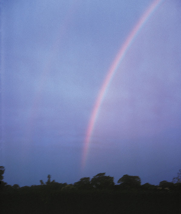
Despite being a familiar sight (figure 1), rainbows are much harder to understand than one might think. The ingredients are, of course, sunlight and rain droplets. Although the Sun’s rays that reach the Earth are essentially parallel, the light impinges on a spherical droplet at a wide range of angles to the surface, where it undergoes refraction. When the light reaches the back of the droplet, two things can happen (figure 2a). The light can either refract and continue in a forward direction out of the drop, or it can be reflected internally, before passing back out through the front surface of the droplet via another refraction. It is this second process – in which light is refracted, reflected and refracted again – that creates the rainbow, which explains why rainbows only appear when one looks away from the Sun into a rain shower.
1 Bow beautiful
(Courtesy: John Hardwick)
Photograph of a rainbow taken by the author using a 45 mm lens at the Daresbury Laboratory, UK, in 1976.
There are, however, innumerable raindrops at many different heights and positions above the horizon. As a result – and because of the many different angles at which the sunlight strikes the droplets’ surfaces – we receive light rays at many different angles to the “antisolar direction”, which is the direction looking away from the Sun towards the shadow of our head. So why does the bright, coloured arc of the rainbow only appear centred on this direction and at a specific and narrow range of angles to it?
Consider first what happens when the incident light strikes the surface of a droplet head on. Some of the light continues straight through the drop, while the rest reflects directly back. For the latter, the “angle of deviation” between the incident and reflected beams is 180°. But as the incident light strikes the droplet at a larger angle, the angle of deviation falls below 180°. When the incident light strikes at even larger angles, the deviation eventually reaches a minimum value, before rising again (figure 2).
2 Rainbow optics
(a) A parallel beam of sunlight striking a spherical rain droplet. Despite being parallel, the light strikes the droplet at a wide range of different angles. The light undergoes refraction as it enters the droplet before undergoing reflection and further refraction. (b) The “angle of deviation” (black line) between the incoming and outgoing rays passes through a minimum value for each wavelength, which is 138° for red light. The intensity of the deviated light (red line) reaches a maximum at this angle and is responsible for the creation of a “primary” rainbow. (c) Different colours have different minimum-deviation angles because the refractive index of water depends on wavelength. The angle between light from the primary rainbow and the “antisolar direction” is 42° for the red bow and 40° for the violet bow. A separate, less intense, “secondary” bow can also be created from light that undergoes not one but two reflections from inside the droplet. The colours of this bow appear in reverse order to the primary bow.
At the minimum-deviation angle the rate of change of deviation angle with incident angle is zero. What this means is that light striking a droplet over a relatively wide range of incident angles emerges concentrated in a narrow – and almost parallel – direction. For example, light rays spanning a 13° interval around the incident angle for minimum deviation are focused down to an emerging beam with an angular width of just 1°. Light travelling in this direction has a relatively high intensity and forms part of the standard – or “primary” – rainbow with which we are all familiar.
Different colours have slightly different minimum deviation angles; it is about 140° for short-wavelength violet light and falls to 138° for red light. The violet component of a primary rainbow is therefore on the bow’s inner side – about 40° to the antisolar direction – while the red component is on the outside at about 42° (figure 2c). Other colours fall in between. As the Sun rises, all that changes is that we see less and less of the rainbow’s arc as the “antisolar point” – the centre of the circle of which the rainbow is a part – and the outer limbs of the bow gradually sink below the horizon. Interestingly, if the Sun is higher than 42° above the horizon, minimum-deviation rays can only be received from drops located at angles below it, which is why rainbows are generally not visible when the Sun is high in the sky at the middle of the day.
Another interesting property of a primary rainbow is that the intensity of light coming from below it is higher than the background intensity from above it. This effect is visible in figure 1. The reason for this is that rain droplets cannot contribute to any light coming from angles above the rainbow because light cannot be bent round a droplet by less than the minimum angle of deviation. Some of the light scattered by the raindrops can, however, reach the observer from below the rainbow, which is therefore brighter than the area above it – but, of course, not nearly as bright as the rainbow itself.
Although a large proportion of light exits the drops after a single internal reflection to form the primary rainbow, some light can undergo two internal reflections. Such twice-reflected rays, which also have minimum-deviation angles and associated intensity maxima, form a “secondary” bow. This appears above the primary bow at an angle of about 52° to the antisolar direction. The secondary bow is fainter than the primary bow and its colours appear in the reverse order. A secondary bow is just visible in figure 1.
What about those light rays that pass out through the droplets in the forward direction after two refractions and no reflection? These have no minimum deviation, which means that this light does not reach a maximum intensity at any particular angle. In other words, if we look towards the Sun through rain, we will see no bright rainbow but just an overall forward glare.
However, in principle, a “tertiary” bow can also be formed after the light has undergone three internal reflections in a droplet. This would occur when looking towards the Sun at an angle of about 40°, but it would be fainter than the secondary bow and obscured by forward glare. There have been some reported sightings of a tertiary bow (D E Pedgley 1986 A tertiary rainbow Weather41 401) but no photographs exist, so far at least!
Supernumeraries and fog-bows
While the main features of a rainbow can be explained by considering the refraction and reflection of light rays, this cannot be the whole story. For example, the intensity of light at the minimum-deviation angle tends to infinity when plotted at finer incident-angle increments. This is clearly not true in reality. Moreover, faint, pale “supernumerary” bows can sometimes be observed below the primary rainbow itself. These are concentric circles of smaller radius than the main rainbow.
The answer to these puzzles lies in the fact that light is not a ray but a wave. When this is taken into account, the unwanted infinity in intensity disappears and is replaced by a maximum in intensity close to the minimum-deviation angle. This maximum can be regarded as a first-order diffraction peak created by the interference of different parts of the wavefront that have reflected off different parts of the droplet’s back surface, have travelled exactly the same distance and are in phase.
Other parts of the wavefront will have different pathlengths, one wavelength more (or less) than the other, and will interfere to create less intense second- and higher-order diffraction peaks, which are the supernumerary bows. The path difference depends on the size of the droplets, which means that supernumeraries are most easily visible when the rain droplets are nearly all the same size. If the droplets were not uniform, the supernumerary bows from different-sized drops would have different angles and could not be clearly distinguished. A search for the origin of supernumerary bows helped in the development of the wave theory of light. This work eventually enabled George Airy, then Britain’s Astronomer Royal, to solve the problem of infinite intensity and explain supernumeraries in 1838.
Wave theory can also explain a rarer form of bow, known as a “fog-bow”. If the rain droplets are large – say about 1 mm in diameter – the first-order diffraction peaks for the different colours of the rainbow are narrow and well separated, which means that the individual colours can be clearly distinguished. However, if the raindrops are smaller than about 50 µm in diameter, the bows of different colours become so broad that they overlap. What one sees in this case is a single, broad white arc. Could this fog-bow be what appears in the famous Buttermere Lake painting by the British artist Joseph Mallord Turner? It shows a white bow above Cromackwater and Buttermere in the Lake District (figure 3).
3 Fog-bow or not?
J M Turner’s 1798 painting Buttermere Lake, with Part of Cromackwater, Cumberland, a Shower shows what appears to be a “fog-bow”. It is created when rain droplets are so small that the different-coloured bows become broadened by diffraction and start to overlap. The painted rainbow is too narrow in width to be a fog-bow. Closer inspection reveals that it also has an anomalously small radius. Turner appears to have been using artistic licence to create the image he wanted. (Courtesy: Tate, London)
But while Turner’s bow is white – and so looks like a fog-bow – the width of the white band is much less broad than is expected for a fog-bow; it is instead about as narrow as the coloured band of a rainbow. On closer inspection the painting is even more curious. It represents a view from near Rannerdale and contains, on the left, a mountain called Fleetwith Pike, which is 544 m above the level of the lake and some four miles in the distance. The angle subtended by the mountain’s vertical extent above the lake is about 5°. If we imagine that the picture has been taken by a camera, the distance from the lake to the summit on the printed page gives us the effective focal length of the camera and, in turn, the angle subtended by the rainbow. A simple calculation indicates that the white bow has an angular radius of about 7.5° – some five times smaller than a standard rainbow (42°).
The colour and anomalous size of the fog-bow are probably because Turner was using artistic licence to create the image he wanted. Indeed, Turner is known to have painted a white rainbow above the forum in Rome, which – based on the shadows that also appear in the picture – was physically impossible (R Lee and A Fraser 2001 The Rainbow Bridge: Rainbows in Art, Myth and Science).
The halo
Raindrops are not, of course, the only form of precipitation. Light can also refract through ice crystals falling through the air. If the crystals all have the same shape, light refracting through them can create a similar effect to the rainbow – a bright, sometimes coloured, bow known as a “halo”. But what causes the phenomenon of minimum deviation, which plays such a key role in the formation of a rainbow? It appears to be ruled out because a single face of an individual crystal forms only one angle of incidence with the rays from the Sun. The answer lies with the fact that the ice crystals tumble through the air, which orients their axes in random directions. Sunlight can therefore strike the crystal faces at many different angles of incidence, allowing minimum deviation to occur.
The most common halo is formed when light passes through an ensemble of poorly aligned hexagonal crystals, which have internal face angles of 120°. Light enters through one face of the crystal and is bent so that it leaves not via the neighbouring face but the next-but-one face. In other words, the crystal is acting like a 60° prism. Simple ray optics reveals that there is a minimum-deviation angle for light passing through such a crystal of roughly 22°. The halo therefore appears when looking towards the Sun and forms a circle of light, where the angle between the direction of the Sun and any point on the halo is 22°. Furthermore, the colours appear in the reverse order compared with a standard rainbow, because there is no reflection off the inside of the crystal’s faces. In practice, however, only the faint inner red rim is usually visible (figure 4).
4 Haloes
Haloes are created when sunlight is refracted and reflected by ice crystals in the atmosphere. The 22° halo, which is seen when looking towards the Sun, is formed from light that refracts through one face and then leaves the crystal by the next-but one face. This photograph of a halo was taken with a 40 mm lens above Zermatt in Switzerland in March 2003. The angle of deviation between the sunlight and the light leaving the crystals is estimated to be 22°. The glare from the Sun has been blocked out by the flag.
The phenomenon of minimum deviation is not the only mechanism that causes haloes. Intensity enhancements in certain directions can also be created by ice crystals as they become aligned while falling through the air. Thin hexagonal plate crystals, for example, will tend to align with the plates horizontal but with the thin, side faces of the hexagon having no preferred angle to the Sun’s direction. This will cause bright regions, dubbed “mock suns”, to appear at the sides of the circular halo. These features can appear as red and yellow smudges of light, without any accompanying circular halo, at an angle of 22° or more from the Sun along the horizontal line through the Sun.
Although one might associate haloes with winter, they can sometimes be seen in the UK during the summer when cirrus clouds are present. These clouds are so high in the atmosphere that they contain ice crystals. I have even seen photos of haloes taken as far south as Corsica in June. But, as one might expect, the most dramatic haloes appear in polar regions, where conditions can be ideal for creating large amounts of ice crystals. Indeed, the geometric theory of haloes was determined as early as 1847 by the French scientist Auguste Bravais, who analysed observations that he and others had made in the Arctic. His work is all the more remarkable considering that these observations were made in the field, without any photographic records whatsoever. Photography for use outside a studio was not developed until the end of the 19th century.
The Whymper apparition
Perhaps the most famous halo was that reported by Edward Whymper following the first ascent of the Matterhorn on 14 July 1865. During the descent, one of the climbers in the forward party slipped and dragged down the other three men to whom he was attached. The rope securing the forward party to the rest of the team then snapped and the four fell down the north face of the mountain to their deaths. Shortly after this tragic incident, Whymper and his two Swiss guides – the Taugwalders – observed an amazing apparition (figure 5a). “A mighty arch appeared, rising…high into the sky,” Whymper later wrote. “Pale, colourless, and noiseless, but perfectly sharp and defined, except where it was lost in the clouds, we watched with amazement the development of two vast crosses, one on either side.” Awestruck, Whymper recognized the phenomenon to be a type of fog-bow that was formed in the opposite (antisolar) direction to the Sun. Although the apparition had no link with the accident, the timing seemed supernatural.
5 Whymper apparition
(a) This woodcut from The Ascent of the Matterhorn (1880, John Murray) shows the magnificent apparition that was reported by Edward Whymper shortly after the first successful ascent of the mountain in 1865. The apparition may have been created by a combination of a fog-bow and ice-crystal arcs. (b) This computer simulation of the Whymper apparition, which was generated using the HALO3 software developed by Les Cowley and Michael Schroeder, was created by the author by tracking the path of light through various arrangements of hexagonal ice crystals (see main text for details). (c) Whymper later drew this sketch of the apparition, which the simulation matches a little better than the woodcut.
In a recent paper I have speculated on the possible origins of the Whymper apparition (J Hardwick 2002 Simulation of the Whymper apparition Weather57 457). Using the HALO3 software developed by physicists Les Cowley and Michael Schroeder, I suggest that it was created by a combination of a fog-bow and ice-crystal arcs. Their program is based on a Monte Carlo technique that tracks rays at a specific solar angle through an ensemble of ice crystals, where the shapes and orientations of the crystals can be chosen. My simulation (figure 5b) tracked rays via the various reflections and refractions of light through cylindrical crystals with hexagonal cross-sections and through others that were a slight variation of these.
The Whymper apparition includes the antisolar horizontal arc and central cross, which can occur if the long axes of the hexagonal cylinders become horizontally aligned. Whymper also observed two bright vertical strips that intersected the horizontal arc to create the two vast crosses. I discovered that these features could be created with hexagonal cylinders that were capped with pyramids – a form of ice crystal known to occur at low temperatures. The cylinder axis pointed horizontally, while two of the six sides were oriented vertically.
Taken together with a fog-bow, the computed result is not dissimilar to the picture that appears in Whymper’s The Ascent of the Matterhorn, especially a later sketch that he derived while writing the book (figure 5c). Although the simulation may seem somewhat contrived, a similar alignment of hexagonal cylinders with two opposite hexagonal faces horizontal was required to explain the features of an intricate halo observed by Captain W E Parry in 1820 during his search for the North West Passage.
The glory of glories
Three days after the Matterhorn tragedy, a separate Italian team made the second ascent from the opposite side of the mountain. During their descent – and at about the same time and altitude that the Whymper apparition had been seen – the party found itself above thick cloud when the climbers observed another strange phenomenon. What they saw this time were their own shadows projected onto the cloud, with rainbow-like rings around their own heads. Known as the “Brocken spectre”, the shadow is said to have been named after an incident involving a climber on the Brocken in the Harz Mountains of Germany. Startled by the appearance of his shadow on a cloud, the climber allegedly fell to his death.
The bright, coloured rings are known collectively as a “glory”. Glories are created when light is backscattered from small water droplets in a cloud. It is a complicated process, but one of the major mechanisms occurs when light strikes a spherical water droplet almost tangentially. The light refracts into the drop and is then internally reflected. But rather than refracting out again when it strikes the surface, it can then travel as a surface wave on the droplet, before emerging at the opposite side of the drop at 180° to the direction in which it arrived (figure 6a). The coloured rings are formed when light that has been backscattered in this way from different parts of the droplet edge interferes (H Bryant and N Jarmie 1974 The glory Scientific American July pp60–71).
Glories are not uncommon. While climbing in Snowdonia in north Wales, for example, I and my fellow climbers emerged from a cloud layer into the Sun, where we were greeted by a glory beneath us. At least three orders of interference rings were visible (figure 6b). The rings are much smaller than those of a rainbow but grow bigger as the droplets shrink in size. Distinct glories – like supernumerary rainbows – therefore require a uniform droplet size. A detailed mathematical explanation of the glory only became possible once physicists had worked out how electromagnetic radiation scatters from spheres, the theory of which is usually attributed to Gustav Mie, who published his work in 1908. However, it was not until 1947 that Hendrik van de Hulst suggested the surface-wave interpretation.
6 Gorgeous glories
(a) Light rays that strike a water droplet at grazing incidence refract into the droplet before being internally reflected and re-emerging from a surface wave 180° opposite. The edge of the droplet can therefore be considered as a coherent source of light, which means that diffraction from an ensemble of such droplets can produce coloured rings, known as a “glory”. (b) This glory was observed by the author while climbing Pen yr Ole Wen – or “hill of the white light” – in Snowdonia, north Wales, in 1993. Analysis of the photograph shows that the first red ring in the picture is at angle, θ, of about 4° from the antisolar direction. Simple diffraction suggests that sinθ≈λ/d. With red light at wavelength λ= 0.65 µm, the diameter, d, of the droplets that created the glory will be about 10 µm. This agrees well with the typical size of mist droplets.
Dew-bows at dawn
Another strange optical phenomenon that can occasionally be seen is the “dew-bow”, which was the subject of a letter last year from Physics World reader and golf enthusiast John Wesson (“Golfing beauty”, March 2003). Wesson described a dew-bow that he had seen while out on a golf course early one morning. “Its hyperbolic shape extended into the distance and its vertex was a short distance from my feet,” he wrote. “As I walked forward, my rainbow moved with me – lasting perhaps 15 minutes.”
A dew-bow is created when light refracts from water droplets located on a horizontal plane, such as the grass of a golf course. As with a standard rainbow, the observer can be pictured as standing at the vertex of a cone and receiving the rainbow light from angles along the cone’s surface. The observer interprets the shape of the light source as the cross-section that is cut through the cone by the plane containing the droplets. So if sunlight strikes the plane at a very shallow angle, for example in early morning, the dew-bow has a hyperbolic shape. Later in the day, if the droplets are still present, the dew-bow will become an ellipse.
Wesson asks why, given that dew is so common, are dew-bows so rare? He has only ever seen one dew-bow, despite being a regular on the golf course. If he had seen many dew-bows of different brightnesses, we might conclude that their formation depends on dew density. But I do not think that the density of dewdrops plays the key role. Dew-bows probably form only when spherical water droplets are present. As with a standard rainbow, this allows sunrays to be internally reflected from the back of the drops. However, experiments with a blade of grass suggest that most drops of water attached to grass are not spheres but hemispheres. Internal reflection would therefore not be possible for the range of angles needed for a complete hyperbola to be seen.
In his classic book Light and Colour in the Open Air, which was originally published in 1954, Marcel Minnaert claims that dew-bows can originate from the fine spherical droplets of dew on cobwebs. But spiders make webs every morning, so why are dew-bows not then seen more often? Maybe it depends on the size of the drops. Perhaps dew-bows are formed only if fine spherical dewdrops condense on and cling to the edges or tip (rather than the faces) of blades of grass. The mystery remains.
Keats’ unweaved rainbow
So has cold philosophy unweaved the rainbow? It seems to me that a fuller understanding of the physical basis of this intricate phenomenon can lead to a proper appreciation of it and also shed light on other, yet more subtle effects that lie outside what Keats called the “dull catalogue of common things”. Each rainbow, halo and glory is unique in that each results from a never-to-be-repeated ensemble of raindrops or ice crystals of particular shapes and sizes. Some forms, like the Whymper apparition, are so rare that you will be lucky to ever seen one in your lifetime.
The physics of the rainbow is perhaps like particle physics, in that each deeper explanation reveals yet another mystery. However, unlike particle physics, we have the final word with Mie scattering theory, which as well as explaining the glory gives a complete theory of the rainbow. But questions still persist. Why, for example, are dew-bows so rare? And why does lightning destroy a rainbow? It appears that some subtleties surrounding the rainbow continue to remain a mystery.
This article first appeared in the February 2004 issue of Physics World. Since then both third-order and fourth-order rainbows have been photographed.
The ability to manipulate and control light is one of the foremost goals of modern optics. However, it is also something that nature perfected a long time ago. About 500 million years ago an evolutionary “big bang” took place, when animal life began to rapidly diversify. This so-called Cambrian explosion is thought to have been triggered when the manipulation of light began to influence the survival of many animals. When it comes to highly advanced optical systems, it seems there is no more experienced an engineer than nature itself.
It is little wonder, then, that the optical engineers of today have started to keep a curious eye on natural optical systems. These systems offer inspiration for new ideas in optical design and could provide shortcuts for developing advanced photonic systems, which one day may even be grown to order. Without doubt, uncovering nature’s optical secrets has been, and will continue to be, a spectacular journey.
Early beginnings
Some of the most interesting optical systems in nature are hard to miss. They are often brightly coloured, metallic looking or strongly iridescent, and stand out from ordinary objects and surfaces that are coloured by pigmentation alone. In the 18th century Robert Hooke and Isaac Newton were among the first to explain the underlying physics of these systems. They correctly predicted that the iridescent colours of peacock feathers and silverfish scales resulted from their physical structure rather than pigmentation. This was a huge leap of understanding, considering that the means of seeing these structures would not be invented for a further two centuries.
It was left to James Clerk Maxwell in the 19th century to develop the set of mathematical tools that now enable us to fully describe the way electromagnetic radiation interacts with matter. This interaction happens all the time, of course, but it starts to get interesting when it takes place in the presence of structural periodicity. Under the right conditions, periodic structure modifies the character of the light that is transmitted, reflected or absorbed by a material. Roughly speaking, the size of the periodicity has to be about the same size as the wavelength of the light involved. An object with a periodicity of a few millimetres to a few centimetres, for example, could control the propagation of microwaves, while the control of optical wavelengths requires periodicities of tens to hundreds of nanometres.
One very important optical constraint for a material, besides its refractive index, is the number of dimensions exhibited by its periodicity. This offers the potential for light to be controlled in one, two or three directions. If 1D or 2D periodicity is limited to the surface of an object, for example, the structure is commonly known as a diffraction grating. If 2D or 3D periodicity exists within the bulk of an object, however, it becomes what is now called a photonic crystal. It is so named because light interacts with the structure in a manner that is analogous to the way that electrons interact with a periodic crystal of ions. Both these processes result in specific bands of allowed energies that are separated by band gaps – regions in which no states can exist. For photonic systems, these are called photonic band gaps and they underpin the way the flow of light is controlled.
Over the last 10 years or so the physics of 2D and 3D photonic crystals has been examined in great detail, and there is currently significant interest in optical technologies based on photonic structures. Synthetic photonic-crystal fibres – which were pioneered by Philip Russell and co-workers at the University of Bath in the early 1990s – could outperform even optical fibres in their ability to transport light (see “Photonic band gaps deliver the goods”, October 2003).
Nanostructure in nature
Nature learned relatively early about the way light interacts with periodic structures due to the evolutionary selection advantages it offers. Highly reflective and coloured surfaces can play an important role in courtship, or in signalling warnings to predators. The first such optical systems appeared as surface diffraction gratings that have been found in Burgess Shale fossils that are 500 million years old. These comprise near-periodic and parallel corrugations on the external hard surfaces of the creatures. Similar periodic systems are also found in some common present-day insects, such as wasps, flies and moths.
Natural photonics Nature has been perfecting the design of optical systems for 500 million years, but physicists are only just beginning to appreciate their complexity. The body of this small Australian beetle, for example, appears metallic green at whichever angle it is viewed from, due to a photonic-crystal structure similar to opal. (Courtesy: A Parker, Oxford University)
Natural surfaces with 2D gratings are not normally designed for bright-coloured reflection. Indeed, provided they comprise the right sort of nanostructure, such gratings can actually reduce the reflection of light at interfaces. Instead, they are found to form antireflection surfaces on many insect eyes, which increase the efficiency of the animal’s vision and reduce unwanted reflection that might attract predators.
Periodicity within materials, rather than on their surfaces, underpins the vast majority of all structural colour in nature (figure 1). This is the case for the 1D multilayer systems responsible for the characteristic colours we associate with nature’s brightest reflectors: butterflies, birds and fish. The materials that make up these multilayers depend on many things, not least the inherent physiology, ecology and environment with which the animal is associated.
1 Periodic design
Natural systems contain nanostructure in a broad variety of structural designs, which can exhibit periodicity in one, two or three dimensions. (a) 1D periodicity in the form of multilayers can be more-or-less flat and continuous, which is the structure responsible for the iridescent colouring in some beetles, plants and diurnal moths. (b) It can also be discretely packaged, such as that found in Morpho butterflies and certain iridescent plant leaves. (c) Some 1D structures contain fibres the orientation of which are continually rotated through the layering. (d) When three individual filters that reflect different colours are stacked on top of one another, they can collectively have a silver or gold appearance. Layers with various thicknesses arranged in a pseudo-chaotic fashion (e), and those arranged in a chirped manner (f), also produce the effect of broadband reflection. These three broadband reflector designs are found in various silver- and gold-coloured fish and insects. (g) Natural 2D periodicity generally comprises close-packed rods of solid material surrounded by air or a liquid with a lower refractive index, which can be found in cat’s eyes and some iridescent bird feathers. (h) 2D periodicity also comes in the form of cylindrical voids that are embedded in a high-refractive-index solid medium, such as those found in the iridescent hairs of certain marine worms. Two principle variations of 3D periodicity are known to exist naturally. (i) Close-packed spheres of solid material generate the iridescence of gem opals and have recently been discovered in certain beetles, while lattices that are filled with hollow voids generate the iridescence of several species of exotic butterfly (j).
In some butterflies, for example, layers of cuticle are intercalated with layers of air in order to generate efficient interference colours, while in many aquatic vertebrates such as fish, the same trick is performed by platelets of solid guanine separated by cytoplasmic fluid. The occurrence of 1D multilayers is extremely common in insects, and a great many of these systems have been investigated thoroughly over the last 40 years. Furthermore, these structures are not limited to fauna but are also found in some plant leaves, berries and algae.
It is difficult to say how long ago selection pressures led to the evolution of 2D and 3D periodic structures within systems. Compared with 1D multilayers they are rather uncommon, and 2D bulk periodicity is most often found in the form of long fibres. Recently Andrew Parker of Oxford University and David McKenzie of the University of Sydney decided to characterize the structures of the hairs of the Aphrodite – a type of worm that inhabits shallow tropical water. What they found was a 2D photonic-crystal fibre.
Each Aphrodite hair contains thousands of hollow, close-packed and longitudinally oriented cylinders of cuticle, each with a diameter of about 230 nm. Bright colours are produced when the cylinders collectively diffract light that is incident on the side of the fibre. Theoretical models suggest that if the structure contained a centrally located defect – such as that in synthetic photonic-crystal fibres – it would be able to guide light down its length. The absence of such a defect, however, suggests that the purpose of these structures is instead for iridescent signalling.
Full 3D periodicity was first investigated in detail in the 1960s, when it was realized that such a structure underpins the iridescence of gem opals. John Sanders, formerly of the Commonwealth Scientific and Industrial Research Organization in Australia, characterized the close-packed arrangement of silica spheres that make up opal structures, and which interact with light to produce their characteristic iridescent colour. More recently, Andrew Parker and co-workers have discovered an analogous 3D sphere structure in a beetle.
A variation of the opal structure – which is sometimes referred to as inverse opal – has been known to exist in certain butterflies for some time, and has been studied in detail by the author and colleagues in the photonics group at Exeter University in the UK. Instead of close-packed spheres, the butterfly structure comprises a lattice of hollow air-filled voids that are formed within a network of interconnecting cuticle. Given the current technological interest in synthetic 3D photonic crystals, these natural 3D systems are quite astonishing for the very fact that they have developed the way they have. The structure appears to be a minor variation of the diamond-like tetrahedral structure, which offers excellent reflectivity over a broad angle range for the particular difference in refractive index between air and the butterfly cuticle.
To further enhance the angle-independent colour, the 3D structure usually appears divided into domains that are about 5 μm in diameter. Each neighbouring domain has the same structure, but they all face in slightly different directions with respect to each other. As a result, the average overall colour effect is essentially angle-independent. Whereas the production of gem opals is understood to be an artefact – a by-product of the way precipitative silica-gel solution settles – the 3D photonic crystals in butterflies and beetles have evolved for a specific biological purpose, which is thought to be associated with visibility.
Natural periodic structures tend to be associated with high reflection or transmission, but creatures have been discovered that can control light in other ways too. Joanna Aizenberg and co-workers at Bell Labs in the US have characterized a 2D surface array of microlenses on the arms of a light-sensitive brittle star – an animal that resembles a starfish. Each lens is a photonic element that is formed from a single anisotropic calcite crystal, and has a characteristic double-lens design with a focal length of a few microns.
The size and profile of each lens is ideal for the task of collecting and focusing light. Their surfaces are shaped in such a way that spherical aberration is minimized, which means that each lens focuses light to a sharply defined point. Furthermore, the orientation of the constituent calcite crystal removes the effect of birefringence, which would otherwise cause different polarizations to behave in different ways and therefore diminish optical function. By focusing incident light onto photoreceptors beneath them, this astonishingly elegant microlens array provides the means to sense light discretely across the arm of the brittle star.
In the completely separate kingdom of plants, analogous but less specialized microlens arrays have evolved in some shade-adapted plants to increase the efficiency of photosynthesis.
Optical nanotechnology and biomimetics
Biomimetics is the extraction of useful design principles from systems that work well in nature. However, humankind’s development of optical systems over the last 100 years reveals something very curious: of all the optical systems developed so far, virtually none appear to have been the direct result of optical biomimetics. We seem to have expended incredible time, effort and expense to produce systems that nature has been using for millions of years.
One of the best examples of this is the traditional multilayer filter, in which layers with alternate high and low refractive indices control the reflection and transmission of light by means of interference. Multilayer filters are an intrinsic component of lasers, telescopes, gravitational-wave detectors and medical probes, but understanding them has developed completely independently of any knowledge of the multilayers commonly found in butterflies and birds.
It is only recently that interdisciplinary research has brought about dramatic discoveries associated with natural optical systems. Despite detailed work from the 1960s onwards by eminent biologists and zoologists, few physicists paid much attention. The analysis of the photonic-crystal-fibre structure of Aphrodite hairs, for example, was taken seriously by physicists because it had strong similarities with the synthetic photonic-crystal fibres developed by physicists a few years earlier.
However, when a little-known scientist named Wolfgang Schmidt looked at the iridescence associated with the hairs of the Aphrodite in the 1940s, the state of optics and related technologies was such that its importance, and indeed elegance, was entirely overlooked. Similarly, recent studies of the 3D photonic-crystal structure of certain butterflies and moths by the author and co-workers at Exeter were preceded by the work of several biologists in the 1960s. Back then, the implications of a natural 3D structure that could effectively control the flow of light in all three dimensions was simply not appreciated.
Today, with tens of thousands of scientists striving to develop optical technologies for a broad variety of applications, we are much more aware of nature’s optical achievements. Taking this one step further and actually learning from nature is, however, only just beginning, and the science of optical biomimetics is very much in its infancy.
Biomimetic myths
Due to popular myth or otherwise, the origins of some modern optical technologies are widely attributed to inspiration from natural optics. In only very few exceptions, however, has this been the case. Take the current use of antireflective materials to enhance the transparency of certain surfaces, in which a smooth and gradual change in effective refractive index is introduced across the interface between two media. Since most transparent glass or plastic is actually not completely transparent – reflecting up to about 8% of light at normal incidence and even more at grazing incidence – improving its transparency can increase the efficiency of, say, a solar cell, that is housed beneath it. This principle, in fact, already enhances the solar gains of some commercial architectural glazing and solar collectors (figure 2).
2 Insect eyes
Insects have already perfected the art of designing antireflective surfaces. (a) Antireflection nanostructures on the lower section of a glass sheet remove the glare that is observed near the upper edge. (b) The antireflective surface region is coated with a nanostructured porous Sol-Gel film, which was produced using the ORMOCER deposition technology and comprising hybrid inorganic and organic composite materials. (c) These synthetic structures are very similar to the natural antireflection nanostructures that are found on many insect eyes, and on transparent wing surfaces. (Courtesy: Fraunhofer Institute for Solar Energy Systems)
As a technology, however, antireflection borrowed little from nature’s expertise. Knowledge of the antireflective effect of the graded index offered by such discrete nanostructure arrays was well known even in the 19th century – long before the development of the electron microscopes required to image them. Even after the advent of the electron microscope, direct biomimicry was not pursued because antireflective periodic structures had already been developed for microwave frequencies. It is no surprise that these had a similar ratio of wavelength to pitch as the antireflective optical nanostructures found in insect eyes.
Where else, then, are the similarities between synthetic and natural optical systems so close that it appears optical biomimicry has occurred? Perhaps an unusual suspect lies in textiles. Some researchers are attempting to link visual and tactile preferences in cloth fibres with fluctuations in the periodicity of their surface irregularities. This has recently led to a new class of textiles – which are referred to in Japan as shin-gosen products – that are more desirable due to their attractive textures and their visual properties.
One particularly intriguing aspect of this research involves fibres of “odd cross-section”. Specialized techniques of extrusion-based manufacturing modify the cross-section of the fibre, which not only allows the fibres to be close-packed but also to produce optical interference and scattering from fine periodic structures within each fibre structure. Curiously, these fine structures also improve the material’s wettability, since capillary forces in the inter-fibre volume are sufficient to carry away liquid perspiration. A designated periodicity within each fibre cross-section, akin to the periodicity associated with the nanostructure on an iridescent Morpho butterfly scale, creates strong colour effects using interference.
A separate range of cloth fibre effects are evident in a product called Microcratered Fibres. The surface of these cloths is uneven on a scale of a few hundred nanometres, which minimizes the scatter of stray light. This property is able to emulate the depth of shade that is associated with quality wool-fibre yarns using only polyester materials. Although its surface very closely resembles that of many black insect surfaces, it is a design that has once again been developed independently of any inspiration from nature. Interestingly, the generic micro-crater design also forms the basis of the ultra-black, metal-alloy surfaces recently developed by Richard Brown and colleagues at the National Physical Laboratory in the UK.
Natural security
But there is an area in which optical biomimicry is starting to work: anticounterfeiting. Many of the recent security measures that have been introduced on banknotes, credit and debit cards, and branded goods rely on complex optical logos, insignia and colour schemes. Nanostructure is pivotal in nearly all these measures (see figure 3), some of which even comprise specialized pigments such as the optically variable ink (OVI) developed by SICPA of Switzerland.
3 Light security
Nanostructure-based anticounterfeiting measures exist to protect various forms of currency, documents, and bank and identity cards. (a) The optically variable devices of OVD Kinegram Technology in Switzerland are among the most effective measures, shown here incorporated in an ID card. Another successful technique (not shown) is to use specialized inks that are deposited in layers, which create iridescent angle-dependent colour effects that can be used to greatly reduce the risk of illegal copying (see text). Natural systems offer ideas for future anticounterfeiting measures. The blue and yellow juxtaposed regions shown in (b), for example, create the overall green appearance of the bright green butterfly wing in (c) through a highly specialized multilayer design system. (d) The multilayer cross-section is responsible for one of the small regions in (b) that comprises a blue annulus surrounding a yellow centre. In addition to the colour effect shown here, the multilayer produces a strong polarization effect that cannot be seen in the image. (Courtesy: OVD Kinegram AG, Switzerland; Nature)
The OVI technique exploits advanced screen-printing methods to produce ink layers of materials with alternating refractive indices, which results in specific iridescent patterns. Other “pearlescent” inks made from clear varnishes are also used. Here, the varnishes are infused with mica flakes that are coated with interference layers of iron and chromium oxides with high and low refractive indices, respectively.
Diffractive, optically variable devices – such as foil patches, stripes and windowed thread – have led to reasonably effective security features on banknotes throughout the world, but they tend not to match the durability of the banknote substrate itself. Embossed holograms and kinegrams have also been used to authenticate bank and credit cards for many years. However, the security they provide is limited by their low surface relief (typically 0.25 μm). This makes the authentication susceptible to counterfeiting because the complete holographic microstructure can be exposed by stripping the hologram from the substrate. Counterfeit tooling can then be made with only the minimum of expertise.
A big improvement in counterfeit deterrence can be gained by the use of high-precision, non-holographic micro-optics and nanostructures, which not only have a surface relief of a few microns but also have sub-surface structure. Some natural optical systems fall straight into this category of micro-optic structure. Chris Lawrence and colleagues at QinetiQ in the UK have been taking specific nanostructure designs directly from butterflies and moths, and trying to replicate them for use as security features in currency.
One specific structure, which was originally characterized by our group at Exeter, comprises a single sculpted multilayer that produces microscopic arrays of two individual structural colours. These colours are juxtaposed in such a way as to produce the appearance of a third colour, in the same way that a colour television creates the full colour spectrum by adding together three individual colours with different intensities. But the specific design of the multilayer of this particular butterfly assigns anomalous polarization properties to only one of the two individual colours. In other words, the reflection of one colour is polarized, while that of the other colour is not. This offers a covert and additional security feature that considerably decreases the risk of counterfeiting.
Designer photonics
Of particular interest in the long term is the way that natural nanostructured systems are self-assembled. In animate systems these schemes are put together in the egg, pupa or as part of normal growth in juveniles. Their formation is therefore controlled at the genetic level, but it also appears to be influenced by external factors such as temperature and nutrition. Other factors, such as exposure to X-rays and laser-mediated heat shock, are also known to alter the development of pigment and structure in specific ways.
Many groups, such as those of Paul Brakefield at Leiden University in the Netherlands and Antonia Monteiro of Buffalo University in the US, are now investigating how variation at the DNA level in developmental genes determines external optical appearance. Once this is completely understood at a fundamental level, it might be possible to change the genetic make-up such that designer nanostructures could be cultured. This is certainly a long way off, but the possibilities are fascinating.
Imagine cultivating a made-to-order 3D photonic crystal on or within an organic light-emitting diode to improve its efficiency, or as part of an optical micro-electromechanical device to improve functionality. Or imagine covering the glass surface of a solar cell with a gene-rich solution that would grow into an antireflective nanostructure array, or onto the surface of a hybrid lens in an advanced camera for it to grow into a large-area microlens array. More useful still, consider the advantages of being able to grow natural photonic-crystal fibres that can guide light, or other 2D crystal structures for optically integrated circuits in all-optical computers.
Rich rewards lie in a variety of established and emerging technologies, not only in taking the design rules and paradigms offered to us by nature’s optical systems, but also in trying to take advantage of some of its self-assembly processes. We have just begun to appreciate how advanced natural optics can be. Even some of our most recent developments in photonic systems, such as photonic crystals and fibres, have in principle already existed for a very long time.
Physicists and engineers would do well not to shy from biological systems but to embrace some of the ideas they offer. There are undoubtedly more lessons to be learned in nature’s optical arena than have come to light in the last few decades. After 500 million years of optical R&D, this is bound to be the case. We should not be surprised at what we find. Given enough time, evolution can do some pretty amazing things.
This article first appeared in the February 2004 issue of Physics World.
Only a few single-phase materials exhibit both strong electric and magnetic properties. Composites that contain both electric and magnetic materials can be made, but this is difficult because the two materials must have compatible lattice structures and must also interact effectively with each other.
Now Ramamoorthy Ramesh at the University of California at Berkeley and co-workers at the University of Maryland, Rowan University, Virginia Tech and Pennsylvania State University have used laser deposition on a ceramic substrate to make a composite ferroelectromagnet from barium titanate and cobalt ferrite. This former is ferroelectric, while the latter is ferromagnetic, and both have similar lattice dimensions.
When they looked at the composite with atomic force and transmission electron microscopes, Ramesh and co-workers found that the two compounds had self-assembled into hexagonal arrays with nanopillars made of cobalt ferrite embedded in a barium titanate matrix. The ferrite nanopillars were evenly sized and spaced about 20 to 30 nanometres apart (see figure).
The composite nanostructure shows three-dimensional heteroepitaxy, which means that the two phases are epitaxial with respect to the substrate and also with respect to each other. This leads to strong mechanical coupling between the two phases, which the team demonstrated by measuring how the magnetic properties of the material changed with temperature. They found a distinct drop in the magnetization around the Curie temperature, which indicated that the ferroelectric and ferromagnetic phases had indeed coupled.
“We now need to get long-range order among the nanopillars, meaning that they arrange themselves into a lattice with a periodicity of say 50 to 100 nanometres,” Ramesh told PhysicsWeb. “We could then have electrically and magnetically tuneable photonic structures.” The researchers now plan to build nanostructures on technologically important substrates such as silicon, and to apply the technique to other materials.
The breakthrough could help physicists improve their understanding of superconductivity and superfluidity. “The strength of pairing in our fermionic condensate would correspond to a room temperature superconductor when adjusted for mass and density,” said Jin at a press conference today. “This makes me optimistic that the fundamental physics we learn through fermionic condensates will eventually help others design more practical superconducting materials.”
Atoms behave very differently at temperatures near absolute zero depending on the value of their intrinsic angular momentum or “spin”. Bosons have spins with integer values in units of the Planck constant divided by 2π, while fermions have spins of 1/2, 3/2, 5/2 and so on. Fermions obey the Pauli exclusion principle, which means that they cannot occupy the same quantum state. However, there are no such restrictions on bosons, so they can all collapse into the same quantum ground state. This process, known as Bose-Einstein condensation, is at the heart of superconductivity – the flow of electric current without any resistance.
Since electrons are fermions they must form Cooper pairs – named after Leon Cooper of the Bardeen-Cooper-Schrieffer (BCS) theory of superconductivity – before they can form a Bose condensate. If this process could be mimicked in a gas of fermionic atoms, it should be possible to learn a great deal more about superconductivity.
Late last year the Boulder team and, independently, a team at Innsbruck managed to form a molecular condensate from a gas of fermionic atoms. The atoms in a molecule are much more strongly bound than those in a Cooper pair. Now, the JILA team has made a condensate from pairs of individual fermionic atoms in a gas. The two fermions are not bound into a molecule but simply move together in a correlated way. Collectively the pair acts as a boson and can therefore undergo condensation.
Jin and co-workers started with a gas of potassium-40 atoms, which are fermions, in an optical trap at a temperature of about 300 nanokelvin. Next, they applied a magnetic field to change the interactions between the atoms and create a “Fesbach resonance” at which the interaction changes from being highly repulsive to become highly attractive. If the value of the magnetic field is carefully controlled, the atoms will form Cooper pairs rather than molecules.
To confirm that they had produced a condensate from pairs of atoms – and not a molecular condensate as in the earlier work – Jin and co-workers actually transformed the pairs into molecules. They did this by applying a second magnetic field – which had exactly the right strength to create molecules – and opening the optical trap at the same time. This allowed them to observe the characteristic shape of a condensate cloud (see figure). According to the JILA team, the change in the magnetic field can cause molecules to form, but the changes are too fast to create a molecular condensate.
“We expect that the fermionic condensates we have observed will exhibit superfluid behaviour,” said Jin. “They represent a novel phase that lies in the crossover between superconductors and Bose-Einstein condensates. This opens up the very exciting potential to study superconductivity and superfluid phenomena under extreme conditions that have never existed before.”
Although gamma-ray bursts were discovered in the 1960s, they are still not fully understood. Some astronomers believe that they happen when a massive star undergoes a supernova explosion at the end of its life and collapses to form a black hole.
On 3 December 2003, a gamma-ray burst lasting about 30 seconds was detected by the Integral satellite in a small galaxy about a billion light years away. A few hours later, Vaughan and colleagues in the US, Denmark and Spain began studying the fading “afterglow” of the burst at X-ray wavelengths with the EPIC cameras on XMM-Newton. They observed a fuzzy halo of X-ray light around the expected position of GRB 031203.
“At first, we thought something had gone wrong with the observation,” Vaughan told PhysicsWeb. “However, we then looked at how this fuzziness changed with time and saw that it was a set of expanding rings.” According to the team, the rings are seen because X-rays from the gamma-ray burst illuminate and scatter dust in our galaxy. X-rays from more distant dust reach Earth later, so it appears that the rings are expanding. Indeed, the halo appears to be expanding at 1000 times the speed of light, but that is merely an optical illusion.
The researchers deduced that there must be two sheets of dust between the gamma-ray source and Earth because they observed two rings (see figure). By measuring the size of the rings, they calculated that the first dustsheet lies about 2900 light years away from Earth and the second at about 4500 light years.
“Dust helps cool gas clouds, which can then collapse to form stars and planets,” said Vaughan. “So knowing where dust is located helps us determine where star and planets are likely to form.” Moreover, the delayed X-rays provide information on the original brightness of GRB 031203. These measurements could help astronomers better understand gamma-ray bursts and learn more on how black holes and galaxies form.
Radioactive tracers are routinely used in biomedical imaging and offer a non-invasive way to look inside the body. Positron emission tomography (PET), for instance, can now achieve resolutions of between 4 and 8 millimetres, but testing this improved resolution involves, among other things, making the sources of the radioactivity compact. Researchers have tried to make such sources by irradiating wires or small particles, but this has proved difficult to do routinely.
Bailey and co-workers soaked commercially available beads of an aluminium-silicon compound in a solution of radioactive technetium-99. The beads had an average diameter of about 2.1 millimetres and contained millions of tiny pores – which is why they are sometimes called molecular sieves. The sieves absorbed and trapped molecules from the solution in their pores, and a typical bead displayed a radioactivity of between 3 to 6 megabecquerels after being soaked for two minutes.
“I have presented this technique at a couple of conferences and am amazed at how much interest it sparks,” Bailey told PhysicsWeb. “Making such small compact sources has clearly been elusive and the fact that this method is so easy – and inexpensive – means that anybody could use it,” he said.
The Australian researchers say that smaller-sized sieves produce higher levels of radioactivity and could therefore be used to test even sharper images. This could important for the new generation of animal scanners that have a spatial resolution of about 1 to 2 millimetres. Moreover, the beads can also absorb fluorine-18, a tracer widely used in PET. The team now plans to investigate whether these sources are visible with other scanning techniques, such as X-ray or magnetic resonance imaging (MRI).



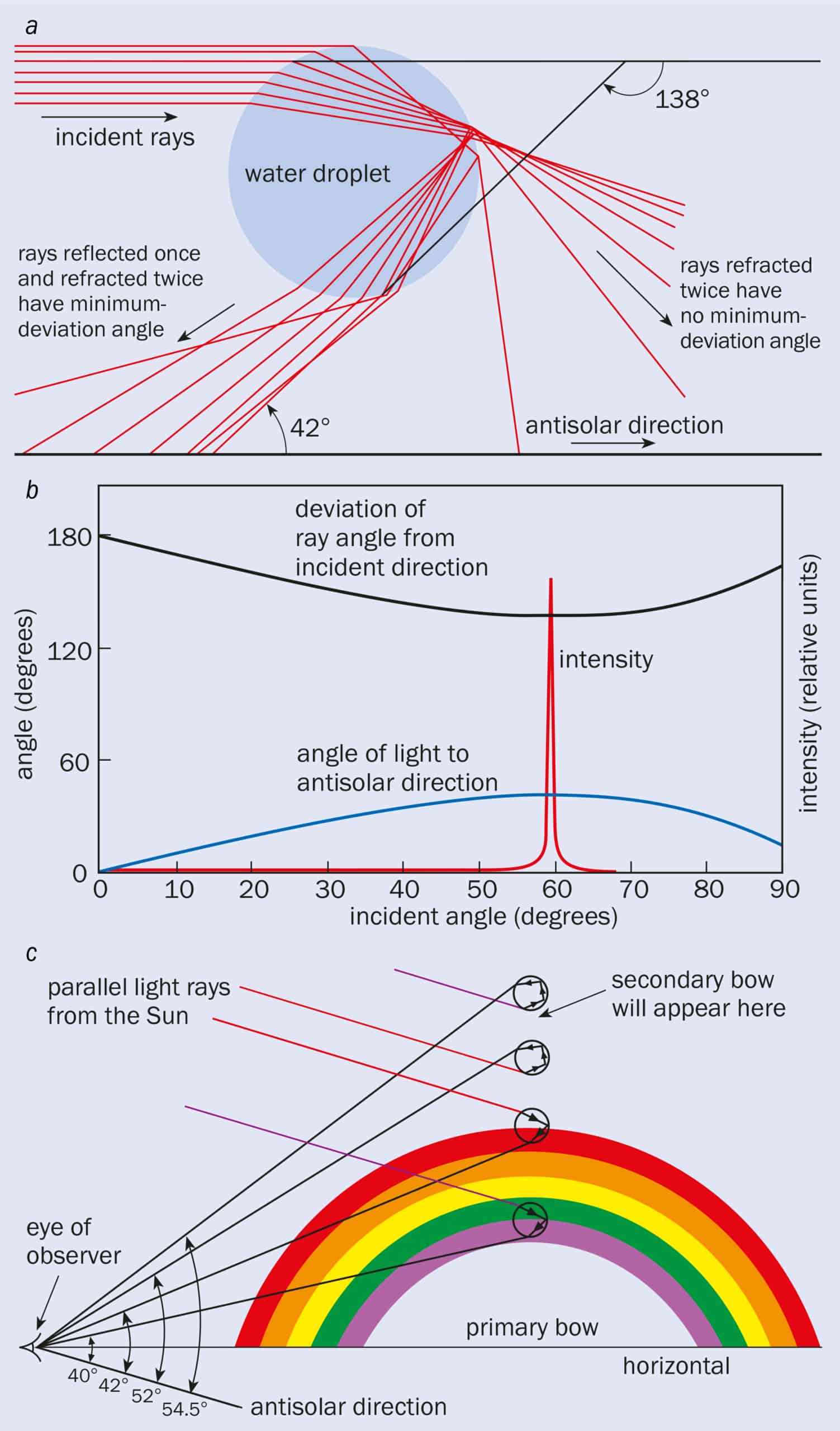 (a) A parallel beam of sunlight striking a spherical rain droplet. Despite being parallel, the light strikes the droplet at a wide range of different angles. The light undergoes refraction as it enters the droplet before undergoing reflection and further refraction. (b) The “angle of deviation” (black line) between the incoming and outgoing rays passes through a minimum value for each wavelength, which is 138° for red light. The intensity of the deviated light (red line) reaches a maximum at this angle and is responsible for the creation of a “primary” rainbow. (c) Different colours have different minimum-deviation angles because the refractive index of water depends on wavelength. The angle between light from the primary rainbow and the “antisolar direction” is 42° for the red bow and 40° for the violet bow. A separate, less intense, “secondary” bow can also be created from light that undergoes not one but two reflections from inside the droplet. The colours of this bow appear in reverse order to the primary bow.
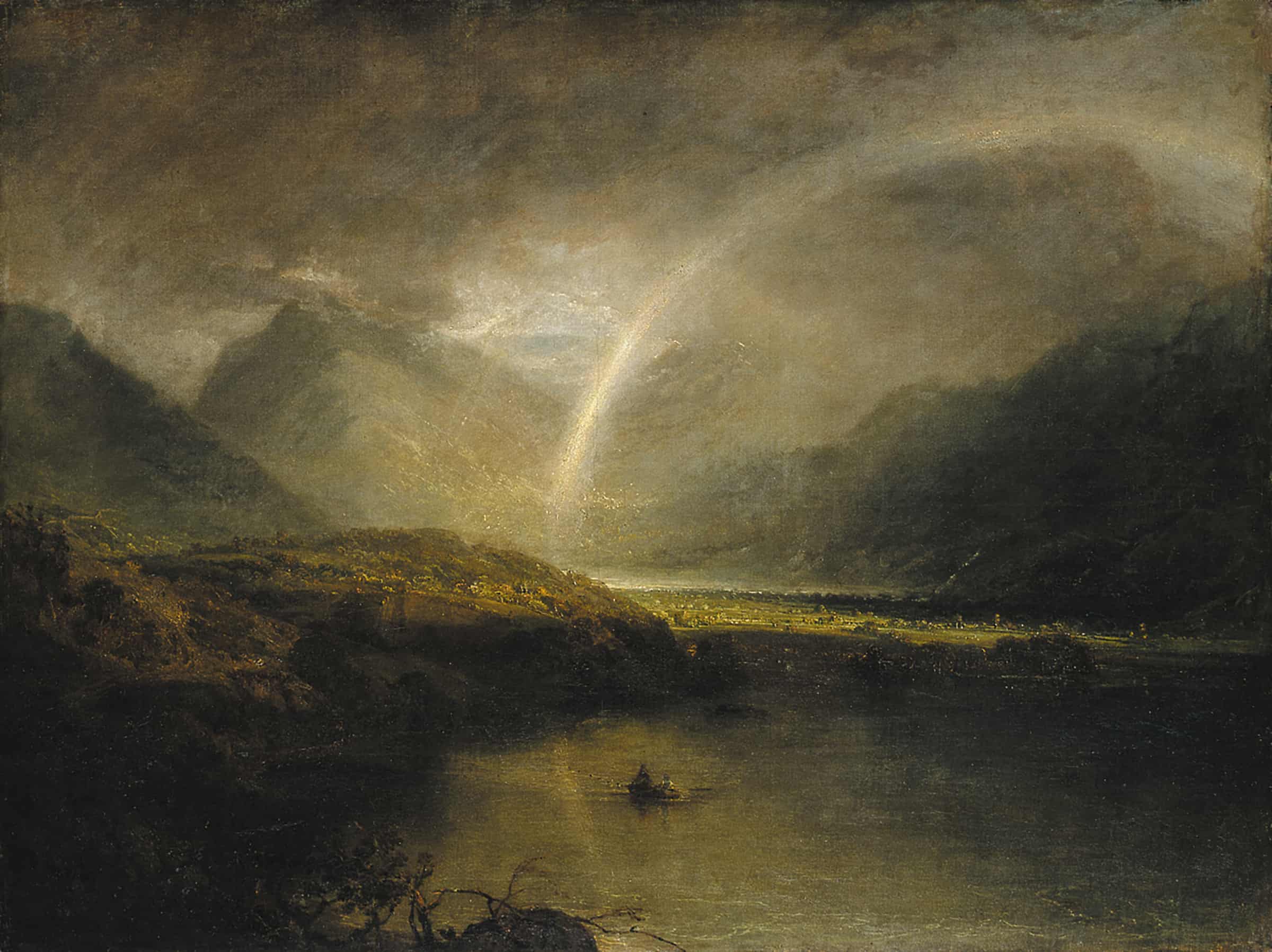 J M Turner’s 1798 painting Buttermere Lake, with Part of Cromackwater, Cumberland, a Shower shows what appears to be a “fog-bow”. It is created when rain droplets are so small that the different-coloured bows become broadened by diffraction and start to overlap. The painted rainbow is too narrow in width to be a fog-bow. Closer inspection reveals that it also has an anomalously small radius. Turner appears to have been using artistic licence to create the image he wanted. (Courtesy: Tate, London)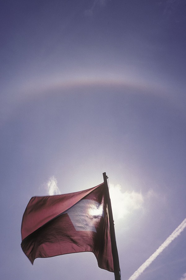
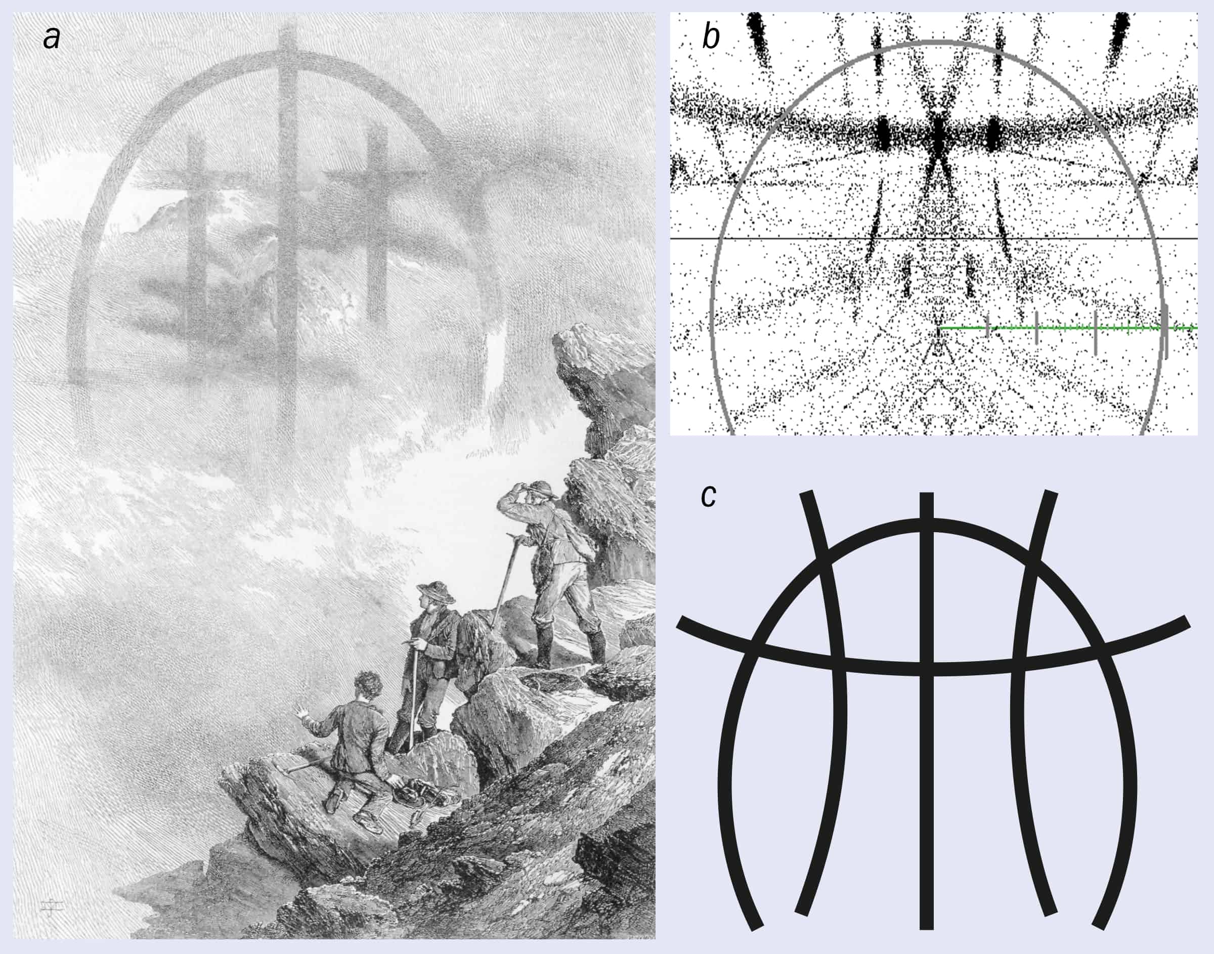 (a) This woodcut from The Ascent of the Matterhorn (1880, John Murray) shows the magnificent apparition that was reported by Edward Whymper shortly after the first successful ascent of the mountain in 1865. The apparition may have been created by a combination of a fog-bow and ice-crystal arcs. (b) This computer simulation of the Whymper apparition, which was generated using the HALO3 software developed by Les Cowley and Michael Schroeder, was created by the author by tracking the path of light through various arrangements of hexagonal ice crystals (see main text for details). (c) Whymper later drew this sketch of the apparition, which the simulation matches a little better than the woodcut.
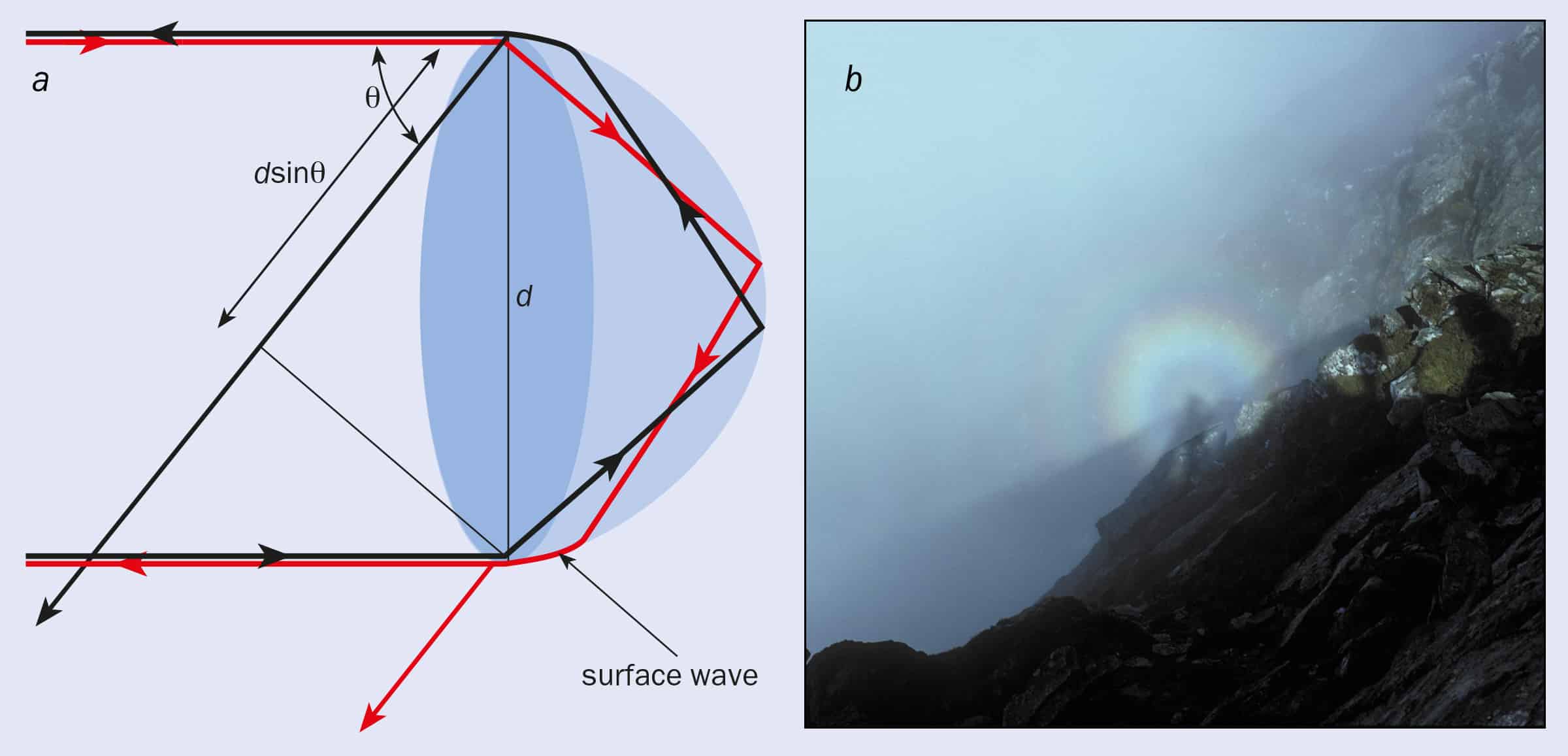 (a) Light rays that strike a water droplet at grazing incidence refract into the droplet before being internally reflected and re-emerging from a surface wave 180° opposite. The edge of the droplet can therefore be considered as a coherent source of light, which means that diffraction from an ensemble of such droplets can produce coloured rings, known as a “glory”. (b) This glory was observed by the author while climbing Pen yr Ole Wen – or “hill of the white light” – in Snowdonia, north Wales, in 1993. Analysis of the photograph shows that the first red ring in the picture is at angle, θ, of about 4° from the antisolar direction. Simple diffraction suggests that sinθ≈λ/d. With red light at wavelength λ= 0.65 µm, the diameter, d, of the droplets that created the glory will be about 10 µm. This agrees well with the typical size of mist droplets.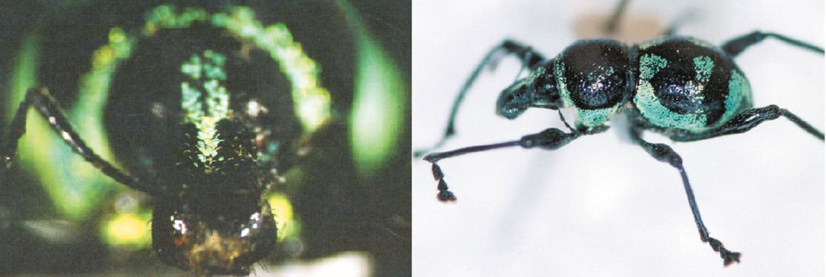
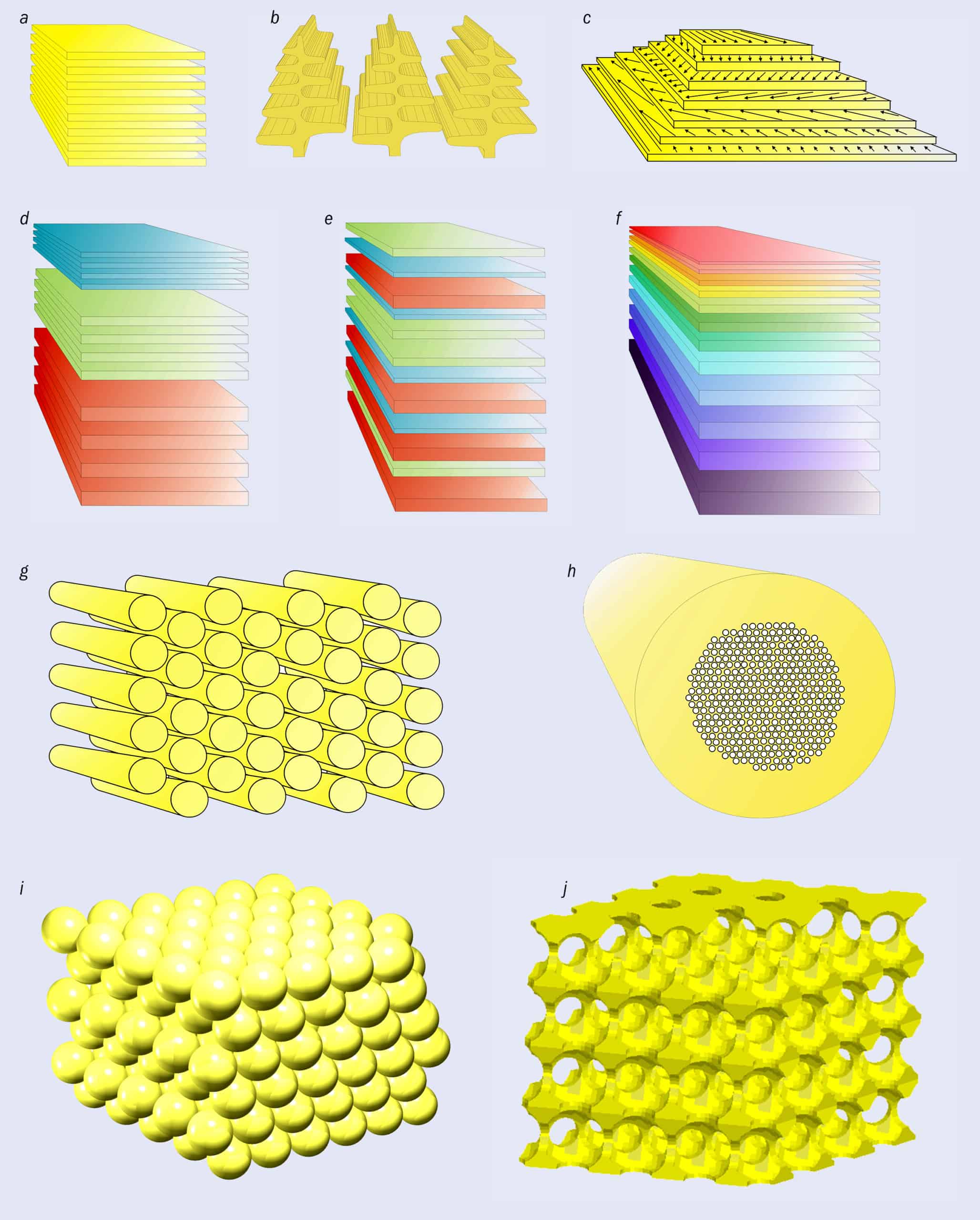 Natural systems contain nanostructure in a broad variety of structural designs, which can exhibit periodicity in one, two or three dimensions. (a) 1D periodicity in the form of multilayers can be more-or-less flat and continuous, which is the structure responsible for the iridescent colouring in some beetles, plants and diurnal moths. (b) It can also be discretely packaged, such as that found in Morpho butterflies and certain iridescent plant leaves. (c) Some 1D structures contain fibres the orientation of which are continually rotated through the layering. (d) When three individual filters that reflect different colours are stacked on top of one another, they can collectively have a silver or gold appearance. Layers with various thicknesses arranged in a pseudo-chaotic fashion (e), and those arranged in a chirped manner (f), also produce the effect of broadband reflection. These three broadband reflector designs are found in various silver- and gold-coloured fish and insects. (g) Natural 2D periodicity generally comprises close-packed rods of solid material surrounded by air or a liquid with a lower refractive index, which can be found in cat’s eyes and some iridescent bird feathers. (h) 2D periodicity also comes in the form of cylindrical voids that are embedded in a high-refractive-index solid medium, such as those found in the iridescent hairs of certain marine worms. Two principle variations of 3D periodicity are known to exist naturally. (i) Close-packed spheres of solid material generate the iridescence of gem opals and have recently been discovered in certain beetles, while lattices that are filled with hollow voids generate the iridescence of several species of exotic butterfly (j).
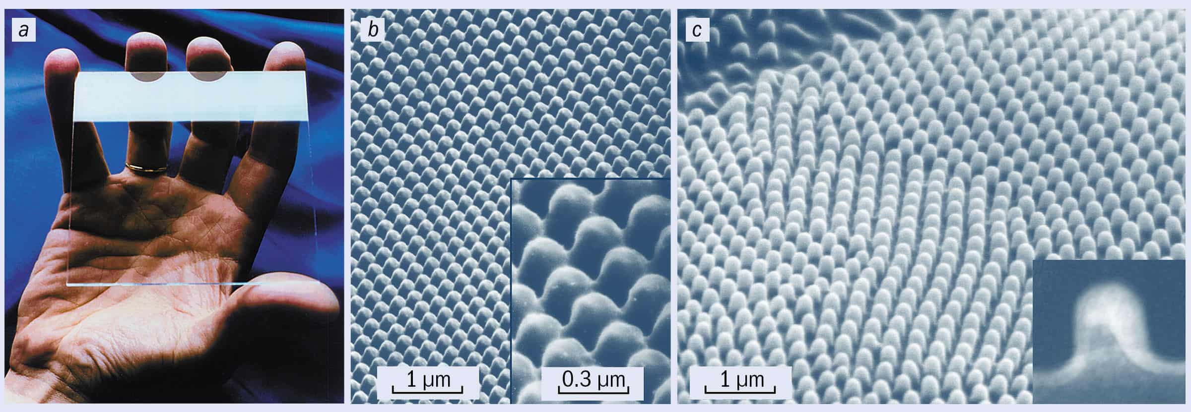 Insects have already perfected the art of designing antireflective surfaces. (a) Antireflection nanostructures on the lower section of a glass sheet remove the glare that is observed near the upper edge. (b) The antireflective surface region is coated with a nanostructured porous Sol-Gel film, which was produced using the ORMOCER deposition technology and comprising hybrid inorganic and organic composite materials. (c) These synthetic structures are very similar to the natural antireflection nanostructures that are found on many insect eyes, and on transparent wing surfaces. (Courtesy: Fraunhofer Institute for Solar Energy Systems)
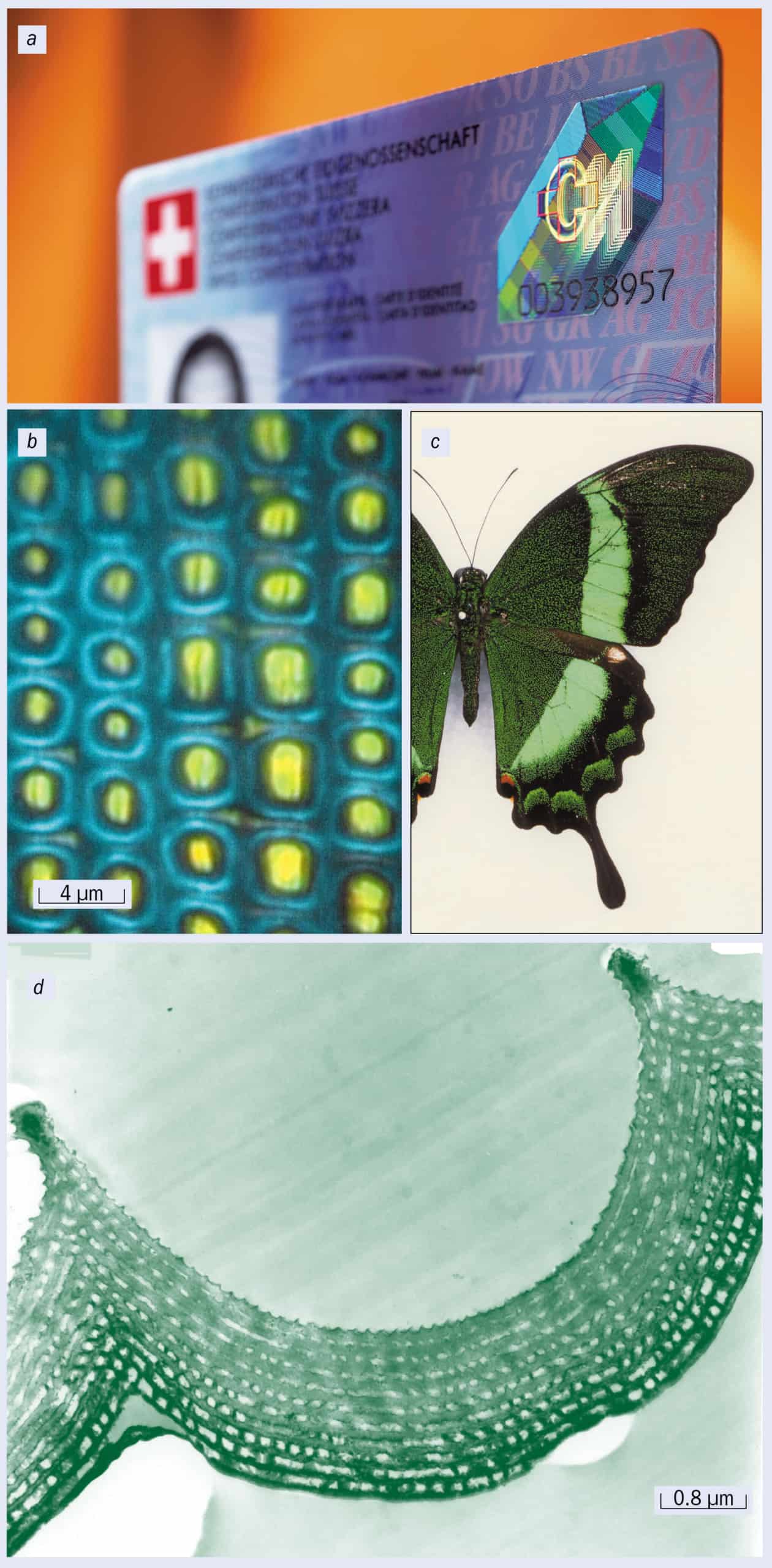 Nanostructure-based anticounterfeiting measures exist to protect various forms of currency, documents, and bank and identity cards. (a) The optically variable devices of OVD Kinegram Technology in Switzerland are among the most effective measures, shown here incorporated in an ID card. Another successful technique (not shown) is to use specialized inks that are deposited in layers, which create iridescent angle-dependent colour effects that can be used to greatly reduce the risk of illegal copying (see text). Natural systems offer ideas for future anticounterfeiting measures. The blue and yellow juxtaposed regions shown in (b), for example, create the overall green appearance of the bright green butterfly wing in (c) through a highly specialized multilayer design system. (d) The multilayer cross-section is responsible for one of the small regions in (b) that comprises a blue annulus surrounding a yellow centre. In addition to the colour effect shown here, the multilayer produces a strong polarization effect that cannot be seen in the image. (Courtesy: OVD Kinegram AG, Switzerland; Nature)