Bose condensation happens in a gas of atoms when the de Broglie wavelength of the atoms becomes comparable with their average separation. All the atoms in the gas then collapse into the same quantum ground state, which gives the condensate many unusual properties. Gases must be cooled to within a fraction of a Kelvin above absolute zero for condensation to occur.
Massimo Inguscio and co-workers at the European Laboratory for Nonlinear Spectroscopy (LENS) and the Istituto Nationale per la Fisica della Materia, both in Florence, the universities of Florence and Padova, and the SISSA institute in Trieste, produced a condensate of rubidium-87 using a magnetic trap and a laser standing wave. The standing wave essentially splits the trap into an array of disk-shaped wells, each about 400 nanometres apart. There are about 200 wells, each containing 1000 or so atoms, and the height of the energy barrier between the wells can be changed by adjusting the laser intensity. Quantum theory allows the atoms to tunnel through the barriers.
In a standard Josephson junction two superconductors or two superfluids are separated by a potential barrier. However, the phase difference between the two sides causes a Josephson current to flow through the barrier. Inguscio and co-workers have observed a similar current of atoms in their device, and they have confirmed that the behaviour of the system is described by a nonlinear Schrodinger equation.
A large number of experiments have already been performed with two- and three-dimensional arrays of Josephson junctions. However, it is difficult to create one-dimensional arrays in these systems. Bose condensates therefore offer the opportunity to observe the large number of new effects that have been predicted to exist in these systems. New effects are expected in quantum phase transitions, nonlinear dynamics, optical fibres, biological molecules and other areas of research.
In 1999 a team of researchers from the Berkeley lab, the University of California at Berkeley and Oregon State University claimed to have detected three atoms of element 118 in collisions between high-energy krypton ions and a lead target. “The observation of a chain of six high-energy alpha decays within about one second unambiguously signalled the production and decay of element 118” said team leader Ken Gregorich at the time. Element 118 was then the heaviest element to have been detected.
In a brief statement submitted to Physical Review Letters, which published the paper reporting the original discovery, the Berkeley team write: “Prompted by the absence of similar decay chains in subsequent experiments, we (along with independent experts) re-analyzed the primary data files from our 1999 experiments. Based on these re-analyses, we conclude that the three reported chains are not in the 1999 data. We retract our published claim for the synthesis of element 118.”
“Science is self-correcting,” said Berkeley director Charles Shank. “If you get the facts wrong, your experiment is not reproducible. There are many lessons here, and the lab will extract all the value it can from this event. The path forward is to learn from the mistakes and to strengthen the resolve to find the answers that nature still hides from us.”
Four years ago the world was stunned to learn that Princess Diana had been killed in a high-speed car crash in Paris. The princess died from internal bleeding that stemmed from major chest, lung and head injuries. Her life might have been saved, however, had paramedics been able to treat her hidden wounds at the scene of the accident. Indeed, internal bleeding is the real killer in many accidents. That is why our group at the University of Washington in Seattle is developing a portable device that is designed to detect and stop internal bleeding using ultrasound.
Doctors and medical practitioners have known for centuries that bleeding can be stopped by applying intense heat. Hot irons, for example, were once used to cauterize wounds sustained on the battlefield. In modern operating theatres, however, surgeons stop injured blood vessels from haemorrhaging by passing an intense electric current through the tissue – a technique known as electrocautery. In both cases, the changes in the structure of the blood vessels and the surrounding tissue are responsible for stopping the haemorrhage. When heat is applied, the blood vessels first shrink, then blood clots form and, finally, the vessels shut off so that blood cannot flow through them.
A sound advantage
Given the number of different methods available to stop bleeding, why do we need another? What advantages does ultrasound offer? All the techniques that are in current clinical use can only stop the bleeding from wounds close to surface of the skin. Lasers and electric currents, for example, can only penetrate some 2–3 mm of tissue. Meanwhile, tourniquets and clamps constrict the flow of blood through the organ or limb as a whole, and run the risk of starving both the healthy and wounded tissue of blood and oxygen, thus causing further damage. None of these techniques are capable of stopping internal bleeding.
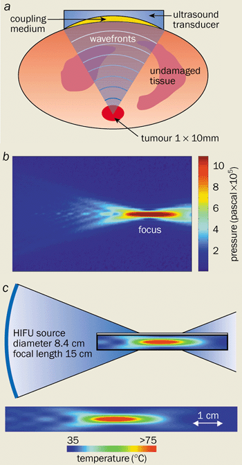
1 Sound idea to treat bleeding vessels (a) The basic principle of acoustic therapy. A high-intensity ultrasound beam is produced by the curved transducer and passes through a coupling medium, such as water. The equipment is set up so that the acoustic energy comes to a focus at the treatment site, where the bleeding is stopped by destroying the local blood vessels. The intervening tissue is not damaged because the ultrasound energy is not focused. (b) The acoustic-field pressure produced by a high-intensity focused ultrasound (HIFU) transducer. The pressure can rise to 1 million pascals at the focus. (c) The thermal effect produced at the focus. Temperatures exceeding 70 °C can be achieved within 1 s.
Ultrasound, on the other hand, can penetrate soft tissue easily and can deliver sufficient energy to cauterize blood vessels located deep within the body (figure 1a). The acoustic energy can also be sufficiently focused so that the injured region can be treated while leaving the healthy tissue unharmed. No other technique can rival the ability of ultrasound to penetrate tissue and to be focused tightly. This technique, known as acoustic haemostasis, thus offers a non-invasive treatment for internal bleeding.
By focusing high-power ultrasound, large amounts of energy can be delivered to specific sites deep within the body. Indeed, the intensity at the focal point is typically 1000–10,000 W cm-2, some four to five orders of magnitude greater than the intensities of diagnostic ultrasound. The waves can be focused using a concave transducer that emits ultrasound waves that converge to a region the size and shape of a grain of rice. The pressure that is generated by the acoustic waves is as high as 1 million pascals at the focal point, but much lower in the surrounding tissue (figure 1b). Such high pressures lead to an intense acoustic beam that produces high temperatures at the focal point due to the absorption of the waves and the conversion of mechanical energy to thermal energy (figure 1c).
How to stop bleeding
So far, investigations into the use of acoustic waves to halt bleeding have concentrated on two very different frequency ranges. Surgeons can currently control bleeding in the operating theatre using a device called a harmonic scalpel, a metal applicator that produces low-frequency ultrasound at 55 kHz. The device, which has been developed by the surgical-instrument manufacturer Ethicon Endo-Surgery Inc., exploits the frictional force between the vibrating tip and the surrounding tissue. The heat that is generated can stop bleeding within a minute, but only at the areas in direct contact with the tip. As such, harmonic scalpels can only treat surface bleeding. Nevertheless, they have found a variety of applications in liver surgery, hysterectomy operations and other surgical procedures.
Our group, however, is concentrating on high-frequency acoustic waves in the 1-10 MHz range. The main application we envisage is in the treatment of bleeding from injured organs and blood vessels. Our studies have concentrated on the liver and spleen, the two organs that are damaged most frequently in trauma. Both organs contain large numbers of blood vessels, which makes it particularly difficult to control bleeding.
Simple wounds to the liver can be treated with electrocautery and biochemical sealants. However, bleeding from more complex injuries is usually stopped by plugging the wound with absorbent material. One disadvantage of this treatment is that the patient needs a second operation some 24-72 hours later to remove the absorber. Meanwhile, the only way to treat patients whose spleen has been severely damaged is to remove part, or even all, of the organ. Surgeons, however, are beginning to reconsider such drastic action because of the important role that the spleen plays in removing worn-out blood cells and other waste material from the blood stream, and because of the risk of post-operative infection. High-intensity focused ultrasound has been demonstrated to effectively stop bleeding from wounds to the liver and spleen of animals, and has the potential to treat humans as well.
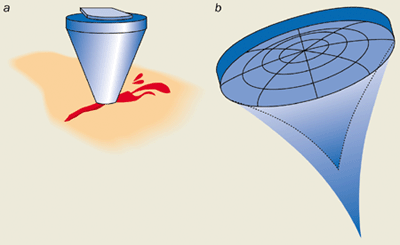
2 Focus on acoustic surgery (a) A high-intensity focused ultrasound (HIFU) transducer in a conical housing can be pointed at an injured artery to stop it bleeding. (b) A multi-element ultrasound device. Such an array allows the focal position to be controlled dynamically by varying the phase of the electrical signals that drive each element of the array.
Our group has used ultrasound transducers at various frequencies (2-5 MHz) and at intensities between 1000-3000 W cm-2 for haemostasis. The transducers are concave piezoelectric crystals that convert an oscillating electric field into a mechanical vibration, which leads to a converging acoustic field. These devices were originally housed in cone-shaped applicators that were filled with water so that the acoustic energy could couple effectively to the tissue (figure 2a).
At first we scanned the focus across the injured surface by manually moving the ultrasound transducer, and brought the bleeding from an incision in the liver under control within 90 s. No bleeding occurred within three hours after the treatment, and we believe that the wound would have stayed “dry” for much longer had we prolonged our experiments. Indeed, recent longer-term studies have demonstrated that no re-bleeding occurs and that the wounds heal as normal.
High-intensity focused ultrasound has also been used to treat bleeding incisions and complex injuries in the livers of pigs. The bleeding from cuts some 50 mm in length and up to 8 mm deep can be brought under control in less than 30 s, and it can be stopped completely within one minute.
Bleeding from major arteries and veins that are several millimetres in diameter has also been investigated. By focusing continuous high-frequency acoustic waves, our group has found that the bleeding from major blood vessels that had been punctured with a thick needle can be stopped in about a minute. We have also looked at more severe cases in which blood vessels had been slashed longitudinally. Such extensive injuries meant that the acoustic energy had to be spread over the entire length of the laceration, some 2-8 mm. We therefore developed a mechanical scanning system to oscillate the point at which the acoustic waves were focused some 15-25 times per second. On average, it took 25 s to completely stop the bleeding.
Interestingly, the treatment time did not change significantly when the animals were injected with a short-acting “anti-coagulant” agent, a drug that thins the blood and thus prevents clotting. This result suggests that acoustic waves can inhibit bleeding independently of the series of biological reactions involving the proteins and enzymes that lead to the formation of blood clots. Alternatively, high-intensity focused ultrasound may accelerate these reactions even when the anti-coagulant is present.
Physical mechanisms behind acoustic surgery
In 1997 our group found that different biological mechanisms stop bleeding in different types of tissue exposed to ultrasound. For example, small blood vessels in the liver collapse, while lacerations in much larger blood vessels fuse to stop the bleeding. These effects may be associated with specific thermal and mechanical mechanisms.
A large number of the structural changes observed in tissue that has been treated with high-intensity focused ultrasound are directly related to the intense heat that is produced when the energy is absorbed. Indeed, the temperature of liver tissue rises to as high as 80 °C at the focal point. As a result, water escapes from the tissue causing the organs to shrink and the blood vessels to collapse under the structural stress and strain. Thermal effects might be responsible for the closure of small blood vessels up to 2 mm in diameter, but they also appear to stem bleeding from major veins. In this case, the surface walls of these blood vessels appear to thicken and an insoluble protein called fibrin precipitates from the blood to form a network of fibres that promotes clotting and acts as a sealant for the wound.
Many of these structural changes are also observed in other techniques that rely on thermal effects, such as laser treatment and electrocautery. However, acoustic therapy also appears to induce a range of mechanical mechanisms that prevent bleeding, including “acoustic streaming” and “cavitation”.
When an intense sound wave passes through a bulk fluid, the absorption and scattering of the energy by the liquid leads to strong and constant flow. Indeed, if an ultrasound wave is directed towards the surface of a fluid, this so-called streaming mechanism produces a fountain. Acoustic streaming brings practical benefits when it comes to stopping bleeding. When the focus of the high-intensity ultrasound is positioned over a bleeding wound, streaming pushes the blood away from the injury, either back into the blood vessel or to the sides.
This action has two advantages. First, it gives surgeons a far better view of the wound since there is no pool of blood to obstruct it. Second, it means that more thermal energy can be applied to the injury itself, thereby accelerating the haemostasis process. The absence of blood surrounding the wound also makes it easier for the walls of the blood vessels to fuse together.
The second mechanical mechanism that appears to stop bleeding is cavitation. The rapid pressure changes induced by ultrasound lead to the formation of cavities or bubbles in the blood. Cavitation was initially thought to have the same damaging effect on blood vessels as it does on the propellers of ships. When the intensity of the ultrasound increases above a certain threshold, the sudden growth and collapse of the bubbles causes extreme pressure changes that can drill holes in the tissue or blood vessels. However, Kullervo Hynynen and co-workers at the Massachusetts Institute of Technology and Harvard University, plus our group, have observed an important new role for cavitation. When the intensity, frequency and duration of the ultrasound pulses are tuned to specific values, the waves can break down the tissue structure to produce tissue “homogenates” that tend to clump together and act as a sealant.
Spreading these tissue homogenates over the injury also seems to seal the wound. Indeed, our group has found that this seal is particularly effective at healing injuries to the spleen that could not be treated using high-intensity focused ultrasound to close the blood vessels. The seal initially looked like a paste covering the wound, but it soon turned into a hard scab that eventually healed as normal.
Many clinicians were worried that the high levels of heat produced by focusing high-intensity ultrasound within tissue would have adverse effects on the blood itself. Recent studies by Sandra Poliachik of the University of Washington at Seattle and co-workers have shown that bursts of ultrasound lasting up to 1 s and with intensities as high as 2000 W cm-2 produce a negligible temperature rise in the blood. Moreover, no changes in the number of blood cells, white blood cells or platelets were observed. However, this situation changed dramatically when a so-called contrast agent was added to the blood. Bubbles in the blood appeared and some 45% of the blood cells were destroyed.
Contrast agents are chemical substances that are used to make ruptured organs easier to identify. These results show that a great deal of care is needed when treating a patient who has been given a contrast agent with high-intensity focused ultrasound, otherwise the sound waves could cause further clinical damage.
Surgical instruments
When it comes to treating bleeding wounds with sound waves, there are two important practical aspects to consider. Clinicians need to ensure that the ultrasound energy couples well to the tissue and that the high-intensity beam can be precisely focused onto the injury in a controlled way.
To satisfy the first of these criteria, the sound waves have to travel from an ultrasound transducer to the focal point through a homogenous medium that has low attenuation and an acoustic impedance that almost matches the tissue under treatment, otherwise the ultrasound is reflected back towards the transducer. Traditionally, water has been the material of choice because it has all the desired acoustic characteristics. Indeed, the majority of acoustic-haemostasis studies have been carried out using a high-frequency ultrasound transducer that is housed in a water-filled plastic cone with a polyurethane membrane at the tip.
In spite of the successful results, there are several drawbacks with water-filled devices. Extra equipment is needed to de-gas and circulate the water to prevent the formation of air bubbles that would scatter the sound wave and spoil the transmission of the acoustic energy. Moreover, the membrane at the tip can easily be damaged, the equipment is cumbersome to use in remote locations, and it is difficult to ensure that it remains sterile.
Our group is investigating different designs of couplers and other materials that could overcome the shortcomings of water coupling. New applicators have been developed that use piezoelectric elements bonded onto aluminium cones that guide and couple the ultrasound energy to the tissue. The cones can have various shaped tips that produce different ultrasound patterns, depending on the type of injury that is being treated. Another approach uses variously shaped devices made from polymer-based gels, which are disposable. One advantage of these couplers is that the concentration of the polymer can be varied so that it matches the acoustic impedance of the injured tissue, thus providing a highly efficient method for transferring the acoustic energy to the tissue. Preliminary results show that the polymer and metallic couplers are at least as effective as water-filled devices at stopping bleeding from injuries to the liver, spleen and arteries.
The other crucial factor is the ability to position the focal point of the high-intensity ultrasound waves precisely. This is important because clinicians need to be able to direct the energy at the bleeding wound to optimize the treatment and to prevent damage to the surrounding tissue. But such dynamic focusing has proved both challenging and time consuming with an ultrasound transducer that consists of a single element with a fixed focus. Hynynen at MIT and Emad Ebbini at the University of Minnesota, among others, have shown that the problems can be overcome with devices that have several transducers and a variable focus (figure 2b). By adjusting the phase of the electrical signal to each of the transducers, clinicians can vary the position of the focal point dynamically without physically moving the ultrasound transducer.
Guiding and monitoring acoustic surgery
Not surprisingly, acoustic surgery can be performed more quickly and effectively when the ultrasound beam is focused accurately on the wound. Bleeding from punctured blood vessels, for example, can be stopped within 3 s if the energy can be focused precisely.
Clearly it helps to monitor the position of beam within the body. In 1999 our group developed a so-called Doppler-guided system to target bleeding vessels. Ultrasound waves reflected from blood gushing out of a ruptured vessel are Doppler shifted to lower frequencies. In contrast, no frequency shift occurs if the beam is reflected from an intact artery. Our system produces an audible sound when the focal point of the high-intensity focused ultrasound is placed directly over a bleeding wound. Indeed, no sound is heard if the focus and the injured site are misaligned by as little as 1 mm. Using Doppler guidance, we found that we could control and completely stop the bleeding some five times faster than by aligning the transducer and wound by eye. Moreover, the technique might also provide a valuable method for monitoring treatment, as the distinct Doppler sound disappears as soon as the bleeding has stopped.
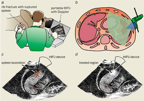
3 Portable operating theatre to the rescue How image-guided ultrasound could treat a casualty with an injured spleen. (a) The injured patient is scanned using ultrasound imaging. (b) The anatomical cross-sectional of the injured spleen. The ultrasound-imaging probe (green) and high-intensity ultrasound device (blue) are coupled together to guide the focal point of the acoustic energy during treatment. (c) An ultrasound image of the spleen before treatment shows lacerations and bleeding. (d) After treatment the bleeding has stopped. The bright region on the diagnostic ultrasound image of the spleen indicates the treated region.
Diagnostic ultrasound is used routinely in hospitals to image internal organs. It also offers a valuable method of targeting bleeding arteries and monitoring them thanks to its real-time-imaging capabilities. Moreover, diagnostic ultrasound is easy to use and can readily be combined with high-intensity focused ultrasound. Our group has devised and tested an image-guided device to treat bleeding by synchronizing bursts of high-intensity sound waves with an ultrasound scanner that produces 2D images of the body. The high-intensity transducer was configured so that the energy was focused in the image plane of the scanner, where it appeared as a bright spot (figure 3).
The technique looks promising, particularly as other ultrasound-imaging and magnetic-resonance-imaging methods do not provide real-time results, which means that patients have to lie perfectly still. Moreover, microscopic examinations have confirmed that no cellular damage occurs in the region where the bright spot appears if the ultrasound has a low intensity. The results suggest that low- and high-intensity sound waves could be used to guide the beam without damaging tissue and for monitoring the treatment.
Image-guided ultrasound has been used to treat injuries to the femoral artery (the main artery in the thigh), wounds left behind when a catheter is removed and blood vessels in the pelvis – all non-invasively.
Clinical and therapeutic applications
The therapeutic applications of high-intensity focused ultrasound were first envisaged by John Lynn in the 1940s, and were later pursued by William Fry, a physicist at the University of Illinois at Urbana Champaign, and his brother Francis, together with Padmakar Lele at MIT. A few years later, the first clinical trials took place in which high-intensity ultrasound was used to treat Parkinson’s disease by creating tiny lesions in parts of the brain that were inaccessible to surgeons. But there is a raft of other possible applications for high-intensity ultrasound.
It could be used to treat internal bleeding in patients who have suffered a major accident in a remote location, on their way to hospital, or even in the emergency room. Indeed, acoustic surgery could save the lives of patients during the “golden hour” – the grace period after a major accident – when steps must be taken to stop casualties from bleeding to death. Ultimately, high-intensity ultrasound might be able to heal wounded organs without the need for invasive surgery.
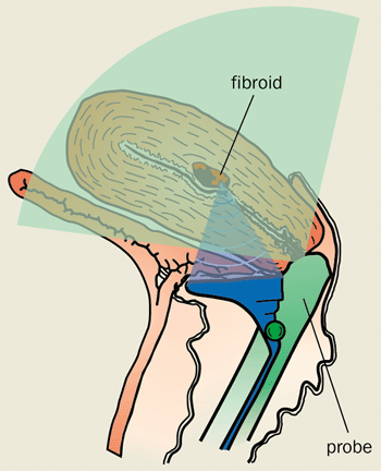
4 Scalpel-free fibroid removal How uterine fibroids could be treated. The transvaginal imaging probe provides a real-time image of the uterus and the fibroids. Meanwhile, a burst of high-intensity focused ultrasound waves (blue) closes the vessels that supply the blood to the tumours and thereby destroys them.
Further possible applications of ultrasound might include cauterizing tissue that is about to be surgically removed in order to reduce the amount of bleeding during an operation. In addition, Gail ter Haar and co-workers at the Royal Marsden Hospital in the UK are aiming to use high-intensity focused ultrasound to treat a syndrome in unborn twins in which there is an imbalance of blood flow between the two babies. Such a condition is often fatal without treatment, but ultrasound could be used to narrow the appropriate blood vessel joining the twins.
It may even become possible to treat tumours by closing the main artery that supplies them with blood using acoustic energy. Other techniques that have been developed to close arteries have demonstrated that the tumours do indeed shrink. However, high-intensity ultrasound appears a more attractive method because it is non-invasive.
Currently, sound waves are used to treat prostate cancer and benign enlarged prostates. Clinical trials are also under way for the treatment of breast tumours and cancers of the kidney, ovaries and liver. Meanwhile our group is developing an image-guided instrument to treat fibroids of the womb without the need for surgery (figure 4).
Studies so far have shown that the spread and re-growth of tumours is significantly reduced after ultrasound treatment and that there are no adverse side effects. Indeed, in a number of studies – including ones by ter Haar at the Royal Marsden – the patients have been treated without an anaesthetic, while the ultrasound transducer was placed against the skin. Although some clinicians are worried that high-intensity ultrasound could cause tumours to spread from one part of the body to another, there is clear evidence to refute this concern.
A sound future
Acoustic therapy has enormous potential to stop bleeding and treat tumours deep within the body in a safe and non-invasive way. The main advantage of acoustic therapy is its ability to treat tissue with sub-millimetre accuracy without damaging the surrounding body. High-intensity ultrasound stands to gain further clinical acceptance and promises to advance the trend towards minimally and non-invasive medical treatment.
DNA plays a pivotal role in biology as the carrier of genetic information in all living species. Recently, however, physicists and chemists have become increasingly interested in the electronic properties of the “molecule of life”. According to some, DNA is a molecular wire that can conduct charge carriers with virtually no resistance. Others, however, find that DNA behaves as an insulator. Experiments are now starting to provide the first clues about the mechanisms that underlie charge transport in DNA.
Despite the current hot debate, the subject is far from new. Soon after James Watson and Francis Crick discovered the double-helix structure of DNA in 1953, Daniel Eley and D I Spivey were the first to suggest that DNA could serve as an electronic conductor. The field has recently been revived with the advent of measurements on single DNA molecules, in particular by Jacqueline Barton’s group at the California Institute of Technology. Barton and colleagues measured the fluorescence produced by an excited molecule and found that it no longer emitted light when attached to a DNA molecule. Their results suggested that this “fluorescence quenching” was due to the charge on the excited donor molecule leaking along the length of the DNA to a nearby acceptor molecule. In other words, they suggested that DNA was a conducting molecular wire.
After much initial controversy, the chemists working on the problem of DNA conductivity are now moving towards a consensus view, as illustrated by the titles of articles in Chemical & Engineering News that have evolved from “DNA: insulator or wire?” in 1997 to “DNA charge migration: no longer an issue” in 2001. It now appears that charge carriers can hop along the DNA over distances of at least a few nanometres. However, the situation among physicists who are measuring electronic transport through DNA molecules over larger distances is much less clear.
Moving electrons from site to site
The process of electron transfer – the movement of charge from one molecule to another, or from one end of a given molecular structure to the other – is one of the most fundamental in chemistry and materials science. Such reactions are crucial in processes ranging from corrosion to photosynthesis. Modern investigations of electron-transfer reactions began in the 1950s with reaction-rate measurements by Henry Taube’s group at Stanford University and others. At the same time, Rudy Marcus at the Polytechnic Institute of Brooklyn and Noel Hush of the University of Sydney began developing theoretical models to describe electron-transfer processes. Their approach combined general ideas of chemical kinetics with specific insights into how the internal motions of molecules can facilitate electronic movement between sites. These mechanistic pictures were later generalized to include quantum-mechanical effects, particularly by Joshua Jortner at Tel Aviv University in Israel and Marcus, and we now have an almost complete understanding of thermal and photoexcited electron transfer.
Consider, for example, an extended molecule with a donor group at one end and an acceptor at the other end. Extensive experimental and theoretical studies have shown that electron-transfer reactions within such a single molecule can occur by two principal mechanisms. The first consists of a single-step electron-tunnelling process from the donor to the acceptor. This process is said to be “coherent” in the sense that the electron does not exchange any energy with the molecule during the transfer, and the electron is never localized. The rate of such reactions decreases exponentially with the distance between donor and acceptor. Therefore, for electron transfer over very long distances, one expects this coherent rate to be insignificant on any reasonable timescale.
The second possible mechanism for long-distance electron transfer is generally referred to as “thermal hopping”. In this incoherent process, the electron is localized on the molecule and exchanges energy with it. Electron transfer proceeds in a multi-step fashion from donor to acceptor. Such hopping processes can transfer charge over far longer distances than the coherent tunnelling process, and the motion can be thought of as diffusive.
Electron transfer within short DNA molecules
The famous double-helix structure discovered by Watson and Crick consists of two strands of DNA wound around each other (figure 1). Each strand has a long polymer backbone built from repeating sugar molecules and phosphate groups. Each sugar group is attached to one of four “bases”. These four bases – guanine (G), cytosine (C), adenine (A) and thymine (T) – form the genetic alphabet of the DNA, and their order or “sequence” along the molecule constitutes the genetic code. In double-stranded DNA, hydrogen bonds between the bases couple the two strands together. The chemical bonding is such that an A base only ever pairs with a T base, while a G is always paired with a C. The base pairs look like the rungs of a helical ladder. Since the phosphate groups on the backbone are negatively charged, the DNA is usually surrounded by positive “counterions”. The DNA structure is ideal for electron transfer because some of the electron orbitals belonging to the bases overlap quite well with each other along the long axis of the DNA. These so-called stacking interactions also underlie many one-dimensional molecular conductors, including one of the most widely studied organic conductors, TTF-TCNQ.
Early measurements of electron transfer in DNA were performed with a variety of techniques, notably by John Warman and co-workers at Delft University of Technology using microwave conductivity. But the intense interest in charge transfer in DNA began with important work by Barton’s group at Caltech, and by Nick Turro of Columbia University in New York and collaborators. These groups reported fascinating distance dependencies, including the apparent coherent transfer over distances as long as 4 nm. The observations led to the suggestion that DNA acts as a “molecular wire”, and that DNA systems represented a “new paradigm” for electron transfer.
The idea that electron transfer is enhanced in DNA appears quite reasonable. Indeed, the possibilities for testing electron transport in DNA are great because the molecule adopts many different structures. These include kinks, bends, bulges and distortions along the molecule, as well as the “polyelectrolyte” character of the double helix, which may lead to the flow of positively charged counterions along the negatively charged phosphate backbone. A major factor is the sequence of the base pairs along the molecule. It is this extensive chemical variability that leads to various different results observed in DNA electron-transfer experiments. Extensive experimental and theoretical work over the past 15 years has led to substantial clarification of charge-transfer mechanisms in DNA. The dominant mechanisms appear to be the two discussed above – coherent tunnelling and thermal hopping.
From contradiction to consensus
Early experiments yielded apparently contrasting results. This was partly due to the variety of DNA sequences, layouts and conditions. To understand why the DNA sequence makes a difference, we need to compare the relative energies of the G-C and A-T base pairs. These energies have now been deduced from computational models, photoemission experiments and electrochemical measurements.
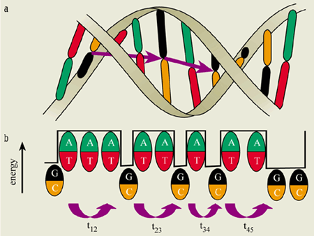
2 Charge transfer along a DNA molecule (a) Charge carriers hop along the length of the DNA molecule from one GC base pair (black and orange) to the next. (b) The relative energies of GC and AT base pairs in this DNA sequence show that a positively charged hole has a lower energy on the GC sites and moves from one GC pair to the next by coherent tunnelling through the AT sites. The overall motion from the first base pair to the last is an incoherent hopping mechanism in which the charged carrier is localized along the path. The total time it takes to move along the path is the sum of the times it takes to jump between individual GC base pairs, t12 + t23 +…+ t45. The process of charge-carrier hopping in DNA is analogous to crossing a river by jumping from one stepping stone to the next.
The important feature is that a hole (i.e. a positive charge) is more stable on a G-C base pair than on an A-T base pair (see figure 2). Also, the energy difference between these two pairs is substantially larger than the thermal energy of the charge carrier. Under these conditions, a hole will localize on a particular G-C base pair. Because the A-T base pairs have a higher energy, they act as a barrier to hole transfer. However, the hole can tunnel in a coherent fashion from the first G-C site to the second, and can then either hop back to the first G-C pair or move on to the next one.
The rate of coherent charge transfer decreases exponentially with the distance travelled. But when the distance between G-C base pairs becomes too long for coherent charge carriers to jump efficiently, thermal hopping becomes the dominant charge-transfer mechanism. As an analogy for such motion, consider leaping across a stream. While it is easy to cross a narrow brook in a single jump, it is impossible to leap across a wide river unless there are stepping stones along the way. The overall time it takes to cross the river is then simply the sum of the times it takes to jump from one stepping stone to the next.
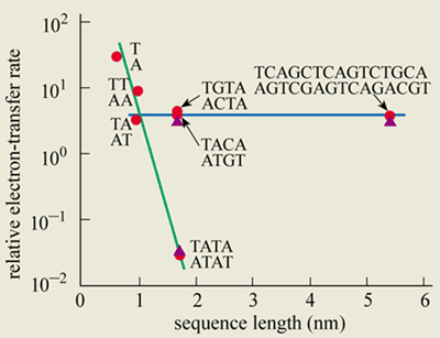
Both charge-tunnelling and thermal-hopping mechanisms have been verified in experiments, notably by Bernd Giese’s group at the University of Basel in Switzerland and by Maibi Michel-Beyerle and co-workers at the Technical University in Munich (figure 3). Meanwhile, George Grüner and co-workers at the University of California at Los Angeles have measured the hopping mobility in DNA and compared it with traditional one-dimensional conductors. And Fred Lewis, Mike Wasielewski and Robert Letsinger at Northwestern University in the US have directly observed both thermal hopping and coherent transfer. Barton and Ahmed Zewail, also at Caltech, have explained their fluorescence-quenching experiments using these two mechanisms.
3 Size and sequence matters The relative electron-transfer rate versus the length of the DNA sequence as measured in experiments by Michel-Beyerle’s group at Munich and Giese’s group at Basel (red). The sequence of bases between the donor and acceptor molecules is denoted next to each experimental point. In coherent transport (green line), the electron tunnels from the donor to the acceptor in a single step without becoming localized on an intermediate site. Charge carriers can tunnel quickly through short DNA strands composed of AT base pairs, but the rate decreases exponentially with sequence length. At longer length scales, charge carriers tend to hop from one GC pair to another (blue line). This incoherent mechanism allows charge to move through much longer DNA strands. The green and blue lines, and the purple points, are from quantum-mechanical computation models by Alex Burin and Yuri Berlin, who work with one of the authors (MR) at Northwestern.
While this picture of coherent transfer and thermal hopping appears to describe the basics, it may not be the full story. For example, what is the role of local thermal motions of the bases? And do the charge carriers have a “polaron'” character: that is do they distort the neighbouring DNA structure? Such open questions are currently under study.
To sum up, DNA serves as an elegant model for one-dimensional charge transport. The two most fundamental processes for electron transfer in extended electronic systems – coherent tunnelling and diffusive thermal hopping – have been clearly demonstrated in DNA charge-transfer studies. It appears that electrons and holes are indeed able to shuttle along a single DNA molecule over a distance of a few nanometres.
Wiring electronics with DNA?
While recent research within the chemistry community seems to converge on a clear picture for the relevant electron-transport processes at the microscopic level, direct electrical measurements on long DNA molecules by a number of physics groups have yielded conflicting results.
A direct measurement of the resistance of single DNA molecules can be made by hooking the molecule up between two metal electrodes and measuring the electric current running through it. Indeed, measurements of small conducting wires – even those formed from single molecules, such as carbon nanotubes – have emerged in the field of mesoscopic physics over the last few years. Such experiments take advantage of the tools developed for nanotechnology, including electron beam lithography for the fabrication of very tiny nanoelectrodes and atomic force microscopy for imaging samples at the molecular level.
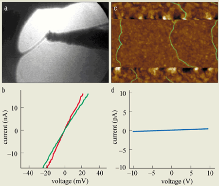
4 Conflicting results for DNA conduction (a) An image of the metal tip used by Fink and Schönenberger at Basel to probe a DNA bundle connected to a metal electrode on the left. The DNA is the thin strand connected between the electrode and the tip. (b) The current–voltage curve measured by the Basel team shows that DNA conducts well and has a resistance of about 1 M ohm. (c) An arrangement of several single DNA molecules attached between two gold electrodes (top and bottom), as studied by Storm and co-workers at Delft. (d) The typical current–voltage curves obtained demonstrate that DNA is an insulator with a resistance greater than 1013 ohm. Note the very different scales in (b) and (d). (Picture credit: John van Noort/TU Delft)
The first direct electrical measurements on small bundles of DNA were made in 1999 by Hans-Werner Fink and Christian Schönenberger at the University of Basel in Switzerland. They developed a special high-vacuum low-energy electron microscope that could image thin free-standing bundles of DNA stretched across a hole in a membrane. They could also measure the conductance (i.e. the inverse of resistance) by touching the DNA bundles with an additional metal tip (figures 4a and b).
The surprising result of this technical tour de force was that DNA bundles almost 1 µm in length appear to behave like an ohmic conductor (i.e. the current rises linearly as the applied voltage is increased). Equally surprising was the low value of the resistance (~1 M ohm), which indicates that DNA conducts well. This was quite unexpected because in the simplest picture one expects that DNA will be a semiconductor with a large energy gap between the valence and conduction bands – in other words DNA is expected to be an insulator.
This finding challenges the current understanding of DNA charge transfer since the molecules used in these experiments had a random sequence of G, A, C and T bases, rather than a large number of G-C pairs. This randomness – together with any additional disorder – should readily localize the carriers and thus prevent the DNA from conducting. The Basel experiments on DNA bundles confirmed earlier experiments by Yoshio Okahata and co-workers at Tokyo Institute of Technology who measured a finite conductivity for stretched films of DNA.
Soon afterwards, Danny Porath and co-workers in one of the author’s (CD) group at Delft made a first attempt at addressing the issue of the DNA sequence using direct-transport experiments. Inspired by the models that emphasize the importance of G-C base pairs for hole transfer through DNA, they made measurements on very short DNA molecules comprising one strand that contained only G bases and a second strand that contained only C bases.
Using a technique called electrostatic trapping, Porath and co-workers placed these molecules between two nanoelectrodes only 8 nm apart. On applying a voltage to the device, they first observed an insulating gap (i.e. no current at low voltage), but above a threshold of about 1 V, they obtained a current through the device. The results suggested that this particular type of DNA – called poly(dG)-poly(dC) DNA – is a large-gap semiconductor (i.e. an insulator). Transport can only occur in these materials when a very large electric field is applied. Such a field may cause the molecular energy bands to align with the energy levels of the electronic carriers in the electrodes, thereby allowing charge carriers to enter the DNA.
More recent experiments by Arnold Storm and co-workers at Delft have measured the electronic conduction at length scales of 40 nm and longer. Convincing images of DNA molecules positioned between nanoelectrodes were obtained with an atomic force microscope, but no conduction was observed for such long lengths of DNA (figures 4c and d). In other words, Storm and colleagues measured an infinite (>1013 ohm) resistance. While these findings contrast with the Basel results, they confirm earlier measurements by Erez Braun and co-workers at the Technion in Israel, who also observed insulating behaviour for DNA some 16 µm in length.
Wide-ranging behaviour
A spectacular report was made earlier this year by Alebker Kazumov, Hélène Bouchiat and co-workers at the Université Paris-Sud. They placed DNA on carbon-covered electrodes that were made of a thin (5 nm) layer of rhenium, a superconducting material. With this set-up they found that room-temperature bundles of DNA have a very low resistance, of the order of 100 k ohm, which approaches the resistance quantum, h/2e2 = 12.9 k ohm, where h is the Planck constant and e is the charge of an electron. (The resistance quantum is the lowest resistance measurable in a perfect metallic wire.) Kazumov and co-workers also reported that DNA supports a “proximity-induced” supercurrent when cooled below 1 K, the temperature at which rhenium becomes a superconductor. This result suggests that DNA behaves as a good conductor and a phase-coherent metal, which is rather puzzling. If the results are confirmed, however, they will be a remarkable finding.
Other experimental results come from the group of Tomoji Kawai at Osaka University in Japan, which has studied DNA extensively using scanning tunnelling microscopy. Recently this group has applied scanning-probe techniques to investigate DNA conduction by measuring the current from the tip of the microscope probe through a DNA bundle connected to a metal strip that acts as a second electrode. Interestingly, they found that the resistance increases exponentially with distance. Indeed, the resistance they measured was high, ranging from 109 ohm to 1012 ohm. They also found that DNA consisting only of C and G bases conducted somewhat better than DNA with A and T bases, which is consistent with the expectations of electron-transfer theory. These interesting findings contrast with results by Pedro de Pablo and co-workers at the Universidad Autónoma de Madrid who found insulating behaviour using the same technique, albeit on “random-sequence” DNA.
DNA can exhibit a surprising range of structural forms and modifications. One interesting example is the replacement of certain hydrogen atoms in the base pairs of the DNA with metal ions. The conduction through such metal-DNA has recently been studied by Andrei Rakitin and co-workers at Brown University in the US, in collaboration with researchers at the University of Saskatchewan in Canada. They reported metal-like current-voltage curves, but they also found that conventional DNA showed low-gap semiconducting behaviour, which again contrasts with measurements by others.
So, where does the field currently stand on the issue of the conduction properties of DNA? It is clear that claims range all over the place: everything from well-insulating behaviour to the support of superconducting currents through DNA has been reported. It is not yet clear whether these opposing results are due to possible artifacts in some experiments, or if they reflect the large “parameter space” of DNA. Possible differences could be due to the base sequence or the length of the DNA, or the properties of the buffer solution in which the DNA is kept. Other factors include the ambient surroundings (whether the experiments are conducted in liquid, air or vacuum), the structural form of the DNA and its organization (whether the bulk material is studied versus bundles or single DNA molecules), and the electrode-molecule interface and so on.
The present authors are unaware of any independent verification of metal-like behaviour and we are confident that long DNA molecules are true insulators, as shown most convincingly by Storm and co-workers. The current status of the field imposes a particularly heavy responsibility on experimentalists. It is more important than ever to devise careful control experiments and for all the findings to be thoroughly reproducible.
Beyond 2001: further along the DNA odyssey
The Watson-Crick double-helix structure for DNA is almost 50 years old. During the last half century, the majority of research into DNA has been devoted to its biological properties, in particular its role in genetic inheritance, disease, aging, RNA synthesis and mutation. Biologists have developed methods to identify and extract sections of DNA and then combine them with other sections with great precision to create new genetic material. Indeed, these same advances in genetic engineering also permit the use of DNA as a component for molecular electronics circuitry.
While it seems unlikely that one can use the intrinsic conductance properties of DNA for single-molecule electronics, Erez Braun, Uri Sivan and co-workers at the Technion have suggested an entirely different approach to DNA electronics by exploiting the molecule’s assembly properties. First they added “sticky ends” to the ends of the DNA – small pieces of single-strand DNA that can bind to “complementary” bases of other sticky ends. Next they attached sticky ends to two metal electrodes so that a single DNA molecule would bridge the gap between the electrodes. The sequence of these single-strand pieces ensured that the binding was highly selective: only those fragments with the matching genetic code coupled to the electrode. After the DNA had assembled, the Technion team replaced the counterions with silver ions so that the DNA could then be used as a seed to grow a thin metallic wire. In this approach, the DNA acts as a linear template for conducting metallic wires.
The highly specific binding between DNA strands may provide a key element in the development of single-molecule electronics. Although many individual components for molecular electronics have been demonstrated recently, a strategy for the assembly of integrated circuits is still largely lacking. The geometry and connectivity of future electronic circuits could perhaps be controlled by DNA self-assembly, rather than by destructive lithography techniques. Indeed, the unique structural properties that control the DNA double helix will almost certainly lead to extensive applications because the synthetic variability and recognition properties of DNA are truly unrivalled by any other molecular structure. One can choose DNA molecules to recognize other DNA molecules, to fill a space in a particular fashion, or to provide a structural scaffolding for the assembly of complex nanostructures.
DNA can be combined with basically any chemical side group imaginable. For example, single-strand sticky ends can be attached to electrically active molecular elements, such as metal clusters, fullerenes or certain molecular switches. These groups can be located at specific sites on the molecules as defined by the sequence of bases. Chad Mirkin, Robert Letsinger and collaborators at Northwestern, as well as Paul Alivisatos’s group at the University of California at Berkeley, have used this idea to prepare nanocomposite structures consisting of gold nanospheres covered with single-strand DNA fragments. They are devising new colloidal materials made from gold spheres joined together with DNA.
The beauty of such materials is that the spacing between the spheres – and thus the thermal, electrical and optical properties – is determined by the nature of the DNA. This spacing can be controlled either statically (by using different sticky ends) or dynamically (by exploiting the melting properties of DNA with changes in temperature or solvent). Such materials can form the basis for remarkably accurate biosensors.
The potential of DNA
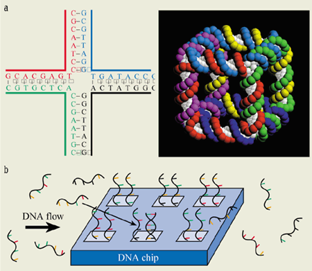
One existing application of the assembly properties of DNA is in so-called DNA chips. These devices exploit the fact that short single strands will bind to other segments of DNA that have complementary sequences, and can thus be used to probe whether certain genetic codes are present in a given specimen of DNA (figure 5).
5 DNA nanotechnology (a) The self-assembly properties of the DNA double helix can be exploited to make a variety of structures. In this case (left), the bases on one molecule (red) bind together with the fragments of two other molecules (green and blue) that have complementary bases. When a fourth fragment is added (black), the result is a cross. Seeman’s group at New York has built three-dimensional structures, such as cubes (right), using this principle. (b) DNA chips are patterned with many short snippets of single-strand DNA, each with a different sequence of bases. When DNA has been extracted from a cell, for example, and labelled with a fluorescent marker, it will only bind to the fragments that have exactly the right genetic code. Currently the chips are read out optically by searching for the fluorescent markers, but the electronic properties of DNA might soon be exploited for this purpose. (Picture credit: N Seeman/New York University)
Microfabricated chips with many parallel DNA probes are becoming widespread in analytical and medical applications. Currently, the chips are read out optically, but further miniaturization might require new read-out schemes, possibly involving the electron-transfer properties of DNA. Such schemes might exploit the different electrochemical responses of single- and double-strand DNA molecules that attach to a surface. However, a detailed understanding of these interfaces remains to be developed.
DNA has the potential for assembling networks with a variety of geometries. Although short pieces of double-strand DNA (below about 50 nm) essentially form a linear stack, intricate spatial structures have been produced by exploiting the self-assembly properties of DNA with sticky ends. In particular, Nadrian Seeman and co-workers at New York University have made intertwined loops, knots, one- and two-dimensional arrays, three-dimensional cubes and nanolattices based on synthetic DNA structures (figure 5). In these cases, the biological properties of DNA are largely irrelevant: the molecule is used simply as a basic building material for nanostructures.
The unique assembly properties of DNA together with its unparalled recognition, optical characteristics, stability and adaptability suggest that DNA may become one of the most important species in the general area of molecular electronics. Often, molecular electronics is viewed only as the formation of logic devices and memories with single conducting molecules. But it can also be defined more broadly as the area of science and technology that studies electronics and sensors based on molecular organization. There is little doubt that DNA is destined to be a major component in the toolkit of molecular electronics.
The behaviour of magnetic vortices controls many physical properties of high-temperature superconductors, including their ability to carry current without resistance – a classic hallmark of superconductivity.
Indeed, vortices provide an ideal platform for the creation and study of novel phases and phase transitions. Now Nurit Avraham at the Weizmann Institute in Israel and co-workers from Russia, Japan, France and the Netherlands have observed a rare phase transition known as “inverse melting” in a magnetic-vortex system for the first time. Meanwhile a collaboration of French, Swiss and US scientists has uncovered a new second-order phase transition between two liquid vortex states in a superconducting yttrium-barium-copper-oxide compound (Nature 2001 411 451; 448).
In the August issue of Physics World, Wai-Kwong Kwok of Argonne National Laboratory, USA, explores the new effects.
Perhaps they’re just shy, but heavy atoms seem very embarrassed when most of their electrons are stripped off. In order to cover their nakedness as quickly as possible, they aggressively try to steal electrons from any source they encounter. Indeed, their electron-capture rates can be orders of magnitude higher than those of ordinary ions. As a result, they offer interesting opportunities to study the influence of extreme electric fields on a variety of physical processes.
The strongest static electric fields that can be studied in the laboratory are those produced by highly charged ions. These fields can approach 1016 V cm-1, nearly 300 billion times larger than the electrical breakdown threshold of air. Such fields can change the electrical structure of space, an effect described by induce quantum electrodynamics (QED).
Until recently, virtually everything we knew about QED effects in atoms was obtained using high-resolution photon spectroscopy. But now Reinhold Schuch and co-workers at Stockholm University have demonstrated that QED effects in highly charged ions can be measured to very high accuracy without detecting any photons, let alone measuring them precisely (E Lindroth et al. 2001 Phys. Rev. Lett.86 5027).
In the August issue of Physics World, John Gillaspy of the National Institute of Standards and Technology, USA, describes the new technique.
Currently there are, at most, five centres operating in the front line of particle physics: CERN and DESY in Europe, Fermilab and Stanford in the US, and KEK in Japan. How many of these laboratories are still with us in a decade or two from now remains to be seen.
The year 2020 might seem a long way away, but that is the timescale that the international particle-physics community is currently contemplating. Indeed, around 1000 American particle physicists gathered at Snowmass in Colorado last month to help map out a 20-year strategy for the future of their subject, and the European Committee for Future Accelerators (ECFA) is also about to report on the future of high-energy physics in Europe.
The next 10 years are already mapped out in broad strokes. The upgraded Tevatron at Fermilab will work at the energy frontier, where it hopes, among other tasks, to confirm the existence of the Higgs bosons, while the B-factories at Stanford and KEK will probe the difference between matter and antimatter in greater detail (see page 11, print version only). At the same time a range of less expensive neutrino and particle astrophysics experiments will tackle questions related to dark matter and other stuff not predicted by the Standard Model of particle physics. Around 2006 the Large Hadron Collider at CERN will take over from the Tevatron at the energy frontier and is likely to operate for a decade.
As part of its plans for the future, the US community is keen ensure that the next really big experiment – a linear accelerator that would collide electrons and positrons at energies of 500 GeV (5 x 10¹¹ electron volts) or higher – is built on American soil. Fermilab has surprisingly emerged at the US’s preferred site for the linear collider, even though it has never played a prominent role in any of the R&D programmes for such a machine. And Stanford has thrown its weight behind Fermilab, much to the chagrin of KEK director Hirotaka Sugawara who is keen for the collider to be built somewhere in the Asia Pacific region – that is somewhere in Japan or California (see page 10, print version only).
Japan is keen to host an international research facility, and its two main targets are the linear collider, which has a price tag of $6bn, and a fusion-energy reactor known as the International Thermonuclear Experimental Reactor (ITER), which is likely to be even more expensive. Japan faces competition from Fermilab and DESY for the first of the projects, and from Canada and France for the second. It cannot afford both.
All agree that the linear collider must be international in a way that no project has ever been before. As Jonathan Dorfan, director of the Stanford Linear Accelerator Center (SLAC), puts it: “[This] is forced on us by the richness of our science and by cost of our science.”
In particular, both the accelerator and the detector must be truly international – in the past the accelerator has usually been built by the host lab, while multinational collaborations have built the detectors. It is also essential that the host country must not benefit unduly from the project. In other words, the host must bear much more of the costs than the other partners. If these two criteria are met, then it does not really matter where the linear collider is built, as long as the best possible machine is built somewhere in the world.
One of the biggest mysteries in physics is why the universe is made entirely of matter, even though equal amounts of matter and antimatter should have been created during the big bang. All the matter and antimatter particles should have annihilated with each other since then, leaving only photons, but somehow one matter particle in a billion or so has survived to create the universe as we know it. Physicists at the BaBar experiment at Stanford in the US and the Belle experiment in Japan have now, for the first time, directly measured the amount of matter-antimatter asymmetry allowed by the Standard Model of particle physics.
“The result determines directly for the first time the magnitude of the fundamental matter-antimatter asymmetry in nature,” says Paul Harrison of Queen Mary College in London, who chairs the UK’s BaBar steering committee. However, as expected, the asymmetries measured by the experiments are not large enough to explain why matter dominates the universe. Physicists will therefore have to look beyond the Standard Model – which can predict the results of most particle-physics experiments to high precision – for an explanation.
What’s the difference
A process called charge-parity (CP) violation is responsible for the difference between matter and antimatter in the Standard Model. CP violation means that the laws of physics change slightly when a particle is replaced by its antiparticle and when all three directions in space are reversed. CP violation was first detected in kaons in 1964, and BaBar and Belle are the first experiments to detect it in another type of particle – the B meson. “The discovery of CP violation in the B system is an outstanding achievement,” says Matthias Neubert, a particle theorist at Cornell University in the US. “The particular significance of the result is that, for the first time, a large CP asymmetry predicted by the Standard Model has been observed.”
CP violation in the Standard Model can most easily be explained in terms of a triangle, with the amount of violation being proportional to the area of the triangle. The base of this “unitarity triangle” is one unit long, so physicists need to measure the values of two other lengths or angles to calculate its area. And the more values they measure, the better they can test the model.
Experimental results are commonly expressed as the sine of 2 ß, where ß is one of the angles. If there is no asymmetry, then sin2ß should be zero. On 6 July, the BaBar team report that sin 2 ß = 0.59, with error bars of 0.14 (arxiv.org/abs/hep-ex/0107013). There is only a 3 in 100 000 chance that the effect is due to statistical fluctuations. And on 23 July the Belle experiment at the KEK laboratory in Japan reported a value of sin 2 ß = 0.99 ± 0.14.
Both colliders have been built to operate as “B Factories” and produce large numbers of B mesons – particles that contain a bottom quark and an anti-down quark – and anti-B mesons. The two collaborations measured sin2ß by detecting the decay of the B particles into J/Psi particles and neutral kaons. CP violation means that, for this particular channel, the B mesons decay slightly slower than their antiparticles.
The Standard Model does not actually predict a value of sin2ß. Rather, like the charge and mass of the electron, it is one of 17 or so parameters that must first be measured in experiments before being included in the model “by hand”. However, both the BaBar and Belle results are consistent with the value of 0.72 suggested by other experiments and calculations based on the model.
CP violation can manifest itself in three different ways. In the indirect process first observed in neutral kaons in 1964, quantum mechanics allows particles to change into their antiparticles and back again in a process known as “mixing”. However, the two rates are different. In direct CP violation, which has also been observed in kaons, particles and their antiparticles actually decay in slightly different ways. However, physicists have so far not been able to perform the complicated calculations needed to convert these experimental results into a measure of matter-antimatter asymmetry.
The type of CP violation observed at BaBar and Belle results from the interference of decays with and without mixing. While it is extremely demanding to measure this form of violation – the B mesons only survive for about 10-12 seconds – it is straightforward to relate the results to the fundamental matter-antimatter asymmetry.
Beyond the Standard Model
The next big challenge for both teams is to measure CP violation in the decay of the B meson into particles called pions. This would measure another angle, alpha, in the unitarity triangle to test the internal consistency of the Standard Model.
“If we get lucky,” says Harrison, “we might find a flaw in the Standard Model, since the dominance of matter in the universe strongly suggests that there are other forms of CP violation in nature that are not included in the theory.”
In 1967 the late Andrei Sakharov showed that, in addition to CP violation, two criteria must be met for matter to dominate the universe: the universe cannot be in thermal equilibrium, and there must exist certain processes that can change “baryon number”. However, reactions that change baryon number have never been observed, although they are allowed by certain extensions of the Standard Model.
“It is possible that the theory of how the matter-antimatter asymmetry in the universe built up may need modification,” adds Harrison. “But either way we win because there is something that we don’t fully understand about the universe and, therefore, there is something new to be found.”
Indeed, most extensions of the Standard Model introduce other parameters that violate CP symmetry. “It is a puzzle,” says Matthias Neubert, “that these effects are not seen in the vast data sets collected by the B factories at Cornell, Stanford, KEK and Fermilab.” Another mystery, he adds, is the fact that CP violation has not be observed in strong interactions, where the effect should be orders of magnitude larger than in weak decays.
“We are sure that the Standard Model must fail at some level and are stunned by the fact that no such failure is observed at the current level of experimental precision. Searches for new physics at the B factories will complement direct searches for new physics in experiments at the energy frontier.”
Self-focusing occurs at high intensities in transparent media when the refractive index is proportional to the intensity. The change in refractive index causes the medium to act as a lens that focuses the laser – hence the name self-focusing. This lens is the ultimate adaptive-optics element as it responds instantly to the shape of the contracting laser beam and thus continually focuses the light. The range of wavelengths in the pulses also increases and, in extreme cases, this spectral broadening can extend all the way from infrared to ultraviolet wavelengths.
High-power femtosecond laser pulses appear to be unique as they carry very little energy (of the order of a millijoule) and yet can achieve very high peak intensities. In a recent experiment, Stelios Tzortzakis and co-workers at the Ecole Nationale Supérieure de Techniques Avancées in Palaiseau, France, provided direct experimental evidence for the creation of the multiple light channels and showed that they eventually merged into one self-guided focused beam that persisted over long distances (Phys. Rev. Lett. 2001 86 5470).
In the August issue of Physics World, Jerome V Moloney of the University of Arizona, USA, sheds light on the subject.
Nearly all electronic and optoelectronic devices are made of semiconductors and rely on the exact control of electric charges. Electrons, however, possess a well defined “spin” angular momentum, in addition to a well defined charge. Their spin is either +1/2 or -1/2: in other words an electron can rotate either clockwise or anticlockwise around its own axis with constant frequency. The two possible spin states naturally represent the “0” and “1” states in logical operations. The ability to exploit this spin in semiconductors promises new logic devices with enhanced functionality, higher speed and reduced power consumption – and might spark a revolution in the semiconductor industry.
So far the problem of injecting electrons with a controlled spin direction has held up the realization of such “spintronic” devices. Two recent experiments represent an important step towards electrical spin injection at room temperature. In the first, Klaus Ploog and co-workers at the Paul Drude Institute in Berlin have demonstrated that room-temperature spin injection is possible (H J Zhu et al. 2001 Phys. Rev. Lett.87 016601). Meanwhile Vincent LaBella and co-workers at the University of Arkansas in the US have shown that the quality of semiconductor surfaces plays a vital role in spin injection (V LaBella et al. 2001 Science292 1518).
Putting the spin into spintronics
For decades spin-polarized electrons have been created in semiconductors simply by illuminating the material with circularly polarized light. However, electrical spintronic devices should not have to rely on optics. A purely electrical method for injecting spin-polarized electrons into semiconductors is needed to guarantee the success of spintronics – and has provided a surprisingly difficult challenge.
So far, two different concepts have been employed to solve the problem. The first approach involves injecting spins from a dilute magnetic semiconductor that acts as an efficient spin aligner when an external magnetic field is applied. This concept works well at low temperatures – almost all the electrically injected electrons have their spins pointing in the same direction. However, it is extremely difficult to implement at room temperature because most of the known magnetic semiconductors lose their spin-aligning characteristics just above liquid-helium temperatures (i.e. above 4 K).
The second approach involves injecting spin-polarized electrons from a ferromagnetic material, where almost all of the conducting electrons are intrinsically aligned. However, this approach also faces problems. Randomly oriented spins – known as magnetically dead layers – in the ferromagnetic material close to the semiconductor interface are a barrier to effective spin injection (see figure a). What is more, theoretical work predicts that spin injection from metals into semiconductors should be virtually impossible. Now an exciting experiment proves the opposite. Ploog and co-workers have demonstrated experimentally that it is possible to inject spin-polarized electrons from iron into gallium arsenide at room temperature.
To get round the problem of spin detection, Ploog and co-workers used a well known trick to prove the existence of polarized electrons. The polarized electrons from the iron were injected into a semiconductor light-emitting device, where they recombined with holes. By measuring the degree of circular polarization of the subsequently emitted light, the Berlin team obtained a direct measure of the spin polarization. The experiment yielded light polarizations of 2% at 25 K and 300 K, which is a good indication that the efficiency of the electron spin injection is much larger at room temperature. Indeed, the injection efficiency must be considerably larger than 2% since the spin lifetime (i.e. the length of time that the electron spin remains aligned in the same direction) in this material is much shorter than the radiative lifetime at room temperature. In other words, the injected spin polarization is partially lost in the semiconductor before the electron recombines with a hole.
Ploog and co-workers also explained the underlying mechanism in terms of a tunnelling process. They argue that the iron and gallium arsenide form a so-called Schottky barrier, a potential barrier that allows electrons to tunnel from one material to the other. This tunnelling process enhances the spin-injection efficiency by reducing the resistance mismatch between the iron and the gallium arsenide – a major obstacle for spin injection according to calculations by Georg Schmidt of the University of Würzburg in Germany and co-workers.
Nearing an answer
As in any good paper, other questions remain to be answered. For example, what is the spin-injection efficiency from the iron into the gallium arsenide given the short lifetime of the spins in the semiconductor? Why is the light polarization independent of temperature? Was the low temperature (50 °C) at which the iron was deposited onto the semiconductor responsible for the efficient transfer of spins between the two materials? How important is the surface quality of the gallium arsenide?
The first answers to this last question have recently come from LaBella and co-workers at Arkansas. They measured the injection of polarized electrons from the tip of a spin-polarized scanning tunnelling microscope into a sample of gallium arsenide with an almost perfectly flat surface, and observed how the spin-injection process was modified by nanoscale step edges. The Arkansas team measured injection efficiencies of 92% on the flat gallium-arsenide terraces and a reduction by a factor of six in a tiny region around the step edges (figure b). They also found that the spin lifetime fell by a factor of 12 at the step edge, and they attribute this reduction to the metallic nature of the step boundary. Although the experiment uses some crude assumptions concerning the spin relaxation times and the radiative lifetime of the electrons, the results reveal the importance of surface quality.
Another recent experiment is by David Awschalom’s group at the University of California at Santa Barbara (I Malajovich et al. 2001 Nature411 770). The researchers there report that polarized electrons continually transfer from a gallium-arsenide reservoir into another semiconductor, zinc selenide. The Santa Barbara group has previously demonstrated that spin transfer from gallium arsenide into zinc selenide is possible. The new experiment reveals that more electrons, and thus a larger spin polarization, drift from the gallium arsenide into the zinc selenide when an electric field is applied. It also demonstrates that the amplitude and the phase of the net spin current can be controlled with a combination of electric and magnetic fields. While these experimental results may look trivial, they are another small step towards spin electronics in semiconductors.
So what is the future of spintronics? Two years ago several experiments demonstrated huge progress in transporting spins over long distances and in high electric fields. This year, electrical spin injection – one of the main remaining obstacles of spintronics – is on the way to being solved. Injecting spins with an efficiency of a few per cent using planar contacts or with the tip of a scanning tunnelling microscope is useless for commercial devices. But techniques for highly efficient spin injection with planar contacts are being developed by various groups and will probably prove successful in the very near future.
The next steps will be the efficient manipulation of the spin orientation and the building of spin memories and spin logic. At that stage, spintronics will face its highest hurdle and have to prove its superiority over conventional electronics.