Sending satellites into space is usually a long and expensive process, so it is essential to ensure things work first time. Giles Case looks at some of the testing techniques used to ensure a high likelihood of mission success

Where does space begin? The answer to this question is a little arbitrary because the Earth’s atmosphere does not abruptly end. In practice, the recognized start of space lies at an altitude of 100 km, known as the Kármán line, which is where the atmosphere becomes too thin to obtain sufficient lift for aeronautical purposes. The atmosphere at this altitude is still enough to create a significant drag on a satellite, which is why satellites must usually fly at some 250–300 km above the Earth’s surface.
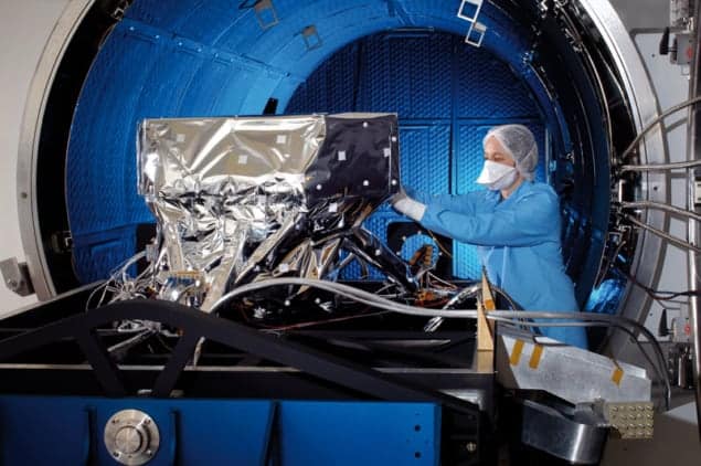
At this altitude, the level of vacuum – about 10–6 mbar – means that the thermal performance of a satellite is dominated by radiative transfer rather than convective transfer, as on the ground. This fact, combined with the complexity and cost of servicing an orbiting satellite, means that anything sent into space has to be rigorously tested in a simulated space atmosphere using a “thermal vacuum test chamber”.
Fixed ultrahigh-vacuum systems used in particle accelerators and other similar systems can be baked at high temperatures to drive off adsorbed water vapour and contaminants from chamber walls and test equipment. This is not possible with space-borne equipment because of the materials used and the highly sensitive nature of some of the components. A typical bake-out of a complete spacecraft is instead usually limited to temperatures of 50–60 °C, which results in the out-gassing load still being very high during testing.
What this means in practice is that high-capacity pumping systems have to be used to reach and maintain the required vacuum levels. Typically, a vacuum level of between 10–7 and 10–5 mbar is needed in a test chamber that may vary in size between that required for a relatively small “cubesat” (measuring 10 × 10 × 10 cm) and one needed to test a large satellite the size of a bus.
For smaller systems, a turbo pump is sufficient to overcome the outgassing load from the chamber and test item, with oil-free systems being used to minimize the contamination risk. For larger systems a combination of turbo pumps, 20 K cryo-pumps and 4 K helium cryo-panels are used to achieve the typical pumping requirement of 500,000 l s–1. Cryo-systems are preferred because they are relatively cheap and are good at pumping water and nitrogen (which are dominant in the chamber at that operating pressure) at high speeds.
Care has to be taken in preparing both the test item and the test chamber itself to ensure that both are clean from a molecular and particulate point of view. For optical instruments, molecular contaminants degrade the overall instrument sensitivity, which is exacerbated at individual wavelengths by specific absorption of particular materials, such as silicones. Particulate contamination contributes to a scattered background, which reduces image contrast and can reduce the life and stability of mechanisms in the optical chain.
Identifying the presence of particulate contamination is relatively easy as clean-rooms can be used to assemble the instruments, with regular inspections helping to maintain cleanliness to the required standard. Preventing and identifying molecular contamination, however, is not so simple. Using known low-outgassing materials as well as proven cleaning and assembly techniques provides a good starting point, but with most items, a bake-out at the maximum temperature of a subsystem is required – as is proof of the outgassing level obtained under common predefined conditions – before the subsystem can be integrated into the spacecraft. Invaluable tools for this work are a residual gas analyser to identify the nature of contaminants and a thermoelectric quartz crystal microbalance to measure the absolute rate of outgassing.
Another key part of the on-ground testing is to simulate the expected thermal conditions the satellite may encounter. This is usually done using a combination of local radiator panels, with a temperature-controlled shroud providing a representative global view. This allows the test item to be driven in a representative way between its expected operating temperatures. During this thermal cycling, functional and optical testing is performed to test and calibrate the onboard systems and ensure all the scientific requirements are met. For a small instrument, this may take just a few days, while a larger calibration campaign may take months of testing. The work may be painstaking, but it is essential to a mission’s success.


