
Squeezing more out of solar power


Scientists in the US have designed a new kind of solar cell that could generate electricity using both the Sun’s light and heat. They claim that the device could be more efficient than either photovoltaic panels or “solar-thermal” plants operating on their own – and potentially allow solar power to compete with fossil fuels in terms of cost per kilowatt-hour.

In an ordinary semiconductor photovoltaic cell, incoming photons excite electrons from the cell’s valence band to its conduction band. The electrons are then collected at an electrode to generate a current. Unfortunately, photons with less energy than the semiconductor’s “bandgap” cannot excite electrons, while photons with more energy than the bandgap lose their surplus energy as heat. The result is that most of the incident solar energy is lost.

This waste heat could, in principle, be recouped by using it to warm up a liquid with a high boiling point, transferring the energy to water and then using the resulting steam to drive a turbine. But in practice attempts to combine photovoltaic and such solar-thermal devices have not borne fruit. The problem is that whereas photovoltaic cells are most efficient at low temperatures (below 100 °C), solar-powered engines work best at high temperatures (above 200 °C).

However, Nick Melosh and colleagues at Stanford University in the US now say they have designed a new kind of device that relies on electron photoexcitation but that actually becomes more efficient at higher temperatures. What they did was to adapt a “thermionic energy convertor” – a device that can convert solar heat directly into electricity. The device was originally developed by both NASA and the Soviet Union to power deep-space missions, although it never succeeded commercially as it could not convert more than 15% of incoming photons into current.

Exploiting the excess

A thermionic energy convertor consists of a cathode and an anode separated by a vacuum gap. A current can flow if a heat source provides electrons in the cathode with enough energy to break free from their host material – usually tungsten – and cross the gap.

In the Stanford design, the cathode is made from a semiconductor and electrons are first excited into the conduction band before crossing the vacuum to reach the anode. With the energy needed to cross the gap coming from the excess thermal energy provided by the incident photons, this “photon-enhanced thermionic emission” (PETE) can, claim the researchers, generate higher voltages than a conventional photovoltaic device with the same bandgap.

The trick, they say, is to make the photons leave the semiconductor rather than remain within it because in a purely solid-state photovoltaic, increased heating can cause electrons to travel away, rather than towards, the cathode, which reduces the output voltage.

Testing times

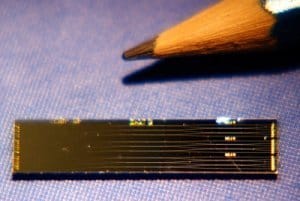
Melosh and co-workers have not yet built a solar cell based on this technology but have tested the principle by placing a caesium-coated gallium nitride wafer inside a vacuum chamber, heating the chamber at temperatures of up to 400 °C, and then illuminating the wafer with different wavelengths of light. They found that the electrons were emitted more readily as they raised the temperature and also that the emitted electrons carried more energy than they started out with. In other words, the electrons picked up thermal energy in addition to the photon energy.

The researchers say that a PETE cell would work best by operating it with a solar-thermal power plant that uses parabolic mirrors to concentrate sunlight. The cell would harvest a portion of the incoming light and output that energy as electricity and then dump its waste heat into the working fluid of the solar thermal plant, where it would drive a steam engine and generate additional electricity. Placed at the focus of each parabolic dish, the cell would be a disc of material with a diameter not more than about 15 cm, the Stanford group estimates.

Melosh says that in this way 50–60% of the incoming solar energy could be converted into electricity, compared to a peak of just 42% achieved to date with photovoltaic cells exposed to concentrated sunlight and a 31% record for solar thermal plants. But he admits that the figure of 50–60% is theoretical. In fact in its experiment, his group achieved efficiencies of just 0.1%.

However, Melosh emphasizes that the experiment was designed to prove the underlying principle and not to achieve high efficiencies, with the caesium-coated gallium nitride having been used to ensure stability at high temperatures. His group is now looking at more high-performance materials, such as gallium arsenide, and Melosh hopes to have a device ready for commercial deployment within three years.

This research is published in Nature Materials.

Satellite image captures Russia ablaze

27117_2.JPG
Courtesy: EUMETSAT

By James Dacey

They are being described as the worst wildfires in modern Russian history and they show little sign of abating.

This image, captured by a EUMETSAT satellite, shows the thick grey smoke that has been sweeping towards Moscow from peat and forest wildfires in central and south Russia. They are a result of the country experiencing its hottest July since records began.

Today, the BBC has reported that Moscow’s daily death rate has now doubled as a result of the continuing heatwave and the wildfire smog. Meanwhile, there is also a state of emergency in the southern Urals as the fires approach Ozersk, a town that closed following Russia’s worst nuclear disaster in 1957.

This image was captured last Wednesday by the AVHRR instrument aboard the EUMETSAT’s Metop-A polar-orbiting satellite, launched in 1986. Moscow is marked by yellow writing towards the bottom left of the image.

How to throw a shot

27117_2.JPG
Shot putters throw furthest at an angle of 37–38°

By Nicola Guttridge

Wimbledon? The World Cup? The Open Championship? Sport isn’t a great interest of mine, but despite my general ineptitude at most athletic activities, a recent paper caught my eye today in which two researchers studied the optimum angle of release in shotput – a problem that has baffled scientists since the 1970s. It’s not 45°, as you might expect. Instead, it turns out that athletes can throw a shot furthest when launched at a lower angle of about 37–38°. So why this difference in angle?

Alexander Lenz at the Technical University of Dortmund and Florian Rappl of the University of Regensburg in Germany puzzled over this and now believe that they have an explanation. It seems that the limitations aren’t in the mechanics but are to do with the human body. What it boils down to is that we humans are much better at pushing outwards than upwards, and so throwing the shot at a slightly lower angle than the expected 45° makes it travel further. To read more about this study, try the arXiv blog post.

As they point out, the human body’s preference for low angles of release is also apparent in weightlifting where weight records for bench pressing are much higher than for when the athlete tries to lift when standing.

Perhaps I should not have been surprised by the non-45° angle for shotputting. Back in 2006 scientists at the University of Brunel calculated the best angle to launch a football at during a throw-in and found it to be 30° to the horizontal – again, disagreeing with the expected angle of 45°. Most of these mistaken predicted angles can be explained by the theoretical calculations treating humans like perfect machines, a little reminiscent of superman – something that I’m sure many footballers would appreciate!

Another post I stumbled upon while reading around the shotput study was one about a completely different type of putting – golf. Robert Grober, an expert on the physics of golf at Yale University, has come up with a model to describe the perfect putt. Apparently the secret to golfing success lies in the behaviour of a simple pendulum being driven at twice its resonant frequency – I’m not sure how practical it’d be to attempt to use Grober’s model on a golf course, but even so it’s quite an interesting read. But then what do I know? I don’t like sport.

2053 Suns

By Michael Banks

In 2003 the photographer Michael White compiled a book, 100 Suns, containing photographs of nuclear explosions drawn from the archives of Los Alamos National Laboratory in New Mexico and the US National Archives in Maryland.

The 100 images were taken in an era of “visible” nuclear testing before such tests went underground in the 1960s.

The images are fascinating, sometimes beautiful, but a chilling reminder of the power of such weapons. Indeed, today marks 65 years since around 100,000 people were killed by the nuclear bomb that was dropped on Hiroshima by a US B-2 bomber in 1945.

This morning I came across a video made by the Japanese artist Isao Hashimoto plotting nuclear weapons tests on a map of the world. As the years tick by from 1965 to 1998 a flash of light shows when a test occurred, where and by who.

The video by Hashimoto covers 2053 nuclear explosions that happened in the time period from the detonations at Hiroshima and Nagasaki in 1945 to the tests by India and Pakistan in 1998 – the period around the Cold War is a particularly active one.

2053 bombs over a 53-year period give an average nuclear detonation once every 9.5 days – a harrowing statistic indeed.

Putting a quantum computer on a chip

chip3.jpg

By Hamish Johnston

When the first transistor was unveiled in 1947 it was a lump of germanium with wires sticking out of it – and it would have been very difficult to convince folks that 60 years later the average person would be carrying millions of transistors around in their pockets.

Just a few years ago a typical quantum processor was a bench-top full of lasers and optics – or perhaps a vacuum chamber containing trapped ions. But now, several labs around the world have worked out how to integrate these components onto a single chip.

A few weeks ago I visited one such lab at the University of Bristol, which is just up the hill from physicsworld.com headquarters.

My host was the physicist Jeremy O’Brien, whose work we have covered in the past – and who has also helped us to make sense of recent developments in quantum computing.

One of Jeremy’s main projects is integrating optical components onto a chip and he showed me a controlled NOT (or CNOT) gate that had been built in his lab (pictured above with a pencil tip). The CNOT gate is a fundamental building block of a wide range of quantum information circuits and could find use in quantum computers, quantum metrology or quantum cryptography.

chip5.jpg

It took O’Brien and his team five years to take the CNOT gate from a bench-top implementation to a chip. On the right is a photo of O’Brien (left) and colleague Xiao-Qi with a typical bench-top implementation (though not of a CNOT gate).

While the Bristol physicists have done well to fit all that kit onto a tiny chip, the job isn’t actually complete. That’s because the device doesn’t include the photon sources and detectors needed to perform a calculation – these are still bench-top components. Adding on these components will take another 5–10 years, according to O’Brien.

And then there’s the sticky issue of making a compatible quantum memory. Strictly speaking, a quantum memory is not needed in a quantum computer because the inputs and outputs could be classical bits of information.

However, a quantum memory would be handy in some cases – and to this end O’Brien and colleagues are looking at the use of quantum dots.

The lab tour was also my first real-life encounter with “blingtronics”, which among other things is focused on the use of diamonds to create quantum bits (or qubits). Diamonds are crystals of carbon that contain a few nitrogen atoms here and there. Each nitrogen atom is accompanying by a neighbouring vacancy (a lattice site with no atom) and resulting “N-V centre” includes an electron spin that is extremely well isolated from the outside world.

This means that the spin could operate as quantum bit of information (or qubit) at room temperature. This is unlike most stationary qubits, which must be cooled to near absolute zero to prevent them from being destroyed by noise.

However, this splendid isolation has its downside because it makes it difficult to use N-V centres in a quantum processor – some interaction is required for information to be exchanged

Now, Mikhail Lukin and colleagues at Harvard University have managed to entangle a single photon with an N-V centre, a process crucial to quantum processing. If you have access to Nature you can read the paper here.

Scientists cast a fly’s eye

Inspired by the eyes of the lowly blowfly, researchers in the US have developed a new way to make highly efficient lenses that could boost the performance of solar cells. Their “bioreplication” technique creates surfaces that mimic fly corneas – and they say it could be automated to mass-produce lenses and other useful structures.

Nature often finds very efficient solutions to engineering problems, and the field of biomimicry is devoted to taking the best from nature and recreating it in the lab. One important way of doing this is bioreplication, whereby an actual biological structure is used as a mould to create replicas. Although bioreplication methods have been improved over the past decade, Akhlesh Lakhtakia of Penn State University, main author of the blowfly study, explains, “All the techniques currently available are not conducive to mass replication.”

The team was inspired to use blowfly eyes when faced with the problem of designing a solar cell with maximum possible efficiency. Each eye has a hemispherical shape and complex hexagonal surface structure, and the researchers believe that stamping the surface of a solar cell with such a pattern would increase its efficiency. “These eyes are perfect for making solar cells because they would collect more sunlight from a larger area rather than just light that falls directly on a flat surface,” explains Lakhtakia.

Coating corneas

Lakhtakia worked with colleagues from Penn State’s Materials Research Institute and the Universidad Autónomia de Madrid in Spain to find a way of making large moulds or dies of the structures that still retained the desired micron-sized features and details. They began by securing an array of nine fly corneas on a glass substrate, and filling their backs with a silicone-based organic polymer to prevent any material that was subsequently applied from seeping behind the eyes. The corneas were coated in 250 nm of nickel using a technique developed at Penn State called conformal-evaporated-film-by-rotation.

The nickel-coated array was then strengthened and formed into a mould by depositing nickel onto its back using a form of electroplating called electroforming. The result is a master template that is half a millimetre thick, but the team says that could be made thicker. The template can be used as either a die to stamp a pattern or as a mould.

Crucially, the team showed that the templates could be used to create polymer replicas of the fly’s eye that include faithful reproductions of features as small as few microns in size. Another important property of the template is that it is strong enough to be used multiple times in the stamping and casting of polymer materials. “We are now working on automating the process,” says Lakhtakia.

Towards industrial bioreplication

Lakhtakia and colleagues now want to make a larger template that includes 30 blowfly corneas in order to show that the technique can be adapted to large-scale or industrial bioreplication.

As well as being used to create better solar cells, Lakhtakia believes that the technique could be adapted for use by police to “read” fingerprints on irregular surfaces that are currently too difficult or complex to examine in detail.

The study of insect eyes is a current hot topic – researchers from Bielefeld University, Germany, have made an artificial bee eye, complete with camera, with the aim of investigating the navigational, sensing and processing skills of bees. The group hopes to extend the study in the future to include UV capability to replicate the colour vision of the insects.

Both experiments are described in full detail in Bioinspiration & Biomimetics.

Fluorescent dye boosts metamaterial performance

Physicists in the US have overcome a major problem that has plagued the designers of “invisibility cloaks” by creating the first negative-index metamaterial (NIM) with a built-in amplifier. It compensates for the strong absorption of light that occurs in optical NIMs, severely limiting their practical use.

Unlike naturally occurring materials, which have a positive index of refraction, a NIM has a structure that is engineered artificially to have a negative index of refraction. NIMs have a number of desirable properties that do not exist in normal materials, including the ability to focus light to a point smaller than its wavelength in a so-called “hyperlens”. Such a device could allow optical microscopes to view much smaller objects than possible today.

NIMs that work at optical wavelengths do have one major drawback – their metal components absorb most of the light that passes through them. One way of getting around this is to incorporate “active” materials such as laser dyes onto the surface of the metamaterial, but physicists have struggled to make this work. Now, however, Vladimir Shalaev and colleagues at Purdue University have found a way around the absorption problem by incorporating a fluorescent dye within the insulating component of their NIM.

Dye in the hole

Their new design is based on the “fishnet” NIM, which Shalaev has been studying in his lab for several years. The structure comprises a layer of alumina sandwiched between two layers of silver – each layer being 50 nm thick. The layers are punctured with oval-shaped holes that are about 200 nm across and repeat every 280 nm in a square array that resembles a net.

The team created the active NIM by etching away much of the alumina, leaving only thin pillars to prevent the structure from collapsing. The resulting gaps were then filled with an epoxy film containing the fluorescent dye Rhodamine 800 (Rh800).

Pump and probe

When these Rh800 molecules are “pumped” with a pulse of 690–nm–wavelength light, they will emit light around 730 nm for several nanoseconds after the pulse is over. If a “probe” pulse of light at about 730 nm is fired at the dye during this time, it will stimulate the emission of light from the dye. The stimulated light is identical to the probe light, the result being the amplification of the probe pulse.

Shalaev and team hoped that amplification by the active epoxy layer would overcome the absorption losses in their NIM. To confirm this they did a “pump-probe” experiment where they fired a 2–ps–long pump pulse at the NIM followed by a 50 ps delay and then a 2 ps probe pulse. The absorption, reflectance and transmission of the probe light by the NIM were measured and the experiment was then repeated without a pump pulse.

The team found that the absorption coefficient of the pumped NIM was about a million times smaller than when no pumping occurs. Indeed, at probe wavelengths of 722–738 nm the combined intensity of the transmitted and reflected light was actually greater than that of the probe pulse – proving that the NIM is working as an amplifier. Metamaterial expert Ulf Leonhardt of St Andrews University in Scotland described the work as a “tremendous achievement”.

Exotic prospects

Shalaev told physicsworld.com that active NIMs could be used to create exotic optical devices including hyperlenses – which can image objects much smaller than is possible using an optical microscope – and nanoscale waveguides that can transmit light with no losses. The technology could even be used to create cloaking devices that bend light around an object, concealing its presence to an observer.

The team’s next goal is to replace the dye with a semiconductor material that can be pumped using an electrical, rather than optical signal. An electrically-driven device would be much easier to integrate with conventional optoelectronics. However, Shalaev believes that optically driven NIMs could also find practical applications.

The work is reported in Nature 466 735.

Spirits are high for superconductivity research

wine.jpg
Alcohol-induced superconductivity (Courtesy: Keita Deguchi)

By Michael Banks

When I was doing my PhD in condensed-matter physics, I remember seeing my colleagues nearly shedding tears after unsuccessfully spending months trying to make a single, small sample of a high-temperature superconductor.

The problem is that once a new superconductor – a material that exhibits zero electrical resistance when cooled below a certain temperature – is discovered then it takes only a few months before every conceivable experiment is performed on it. Time, as well as the quality of the sample, is everything.

So this morning I couldn’t help but raise a smile while skimming through the arXiv preprint server when I found a paper by researchers in Japan who have studied the effect of growing a new type of superconductor in “hot commercial alcohol drinks” such as red and white wine, beer, Japanese sake, whisky and shochu.

By heating powders of iron, tellurium and tellurium sulfide together at 600 °C they produced samples of FeTe0.8S0.2. But instead of performing experiments on these samples, they decided to put them into 20 ml glass bottles containing different alcoholic beverages.

They found that when they put the sample in an ethanol-water mixture, only around 10% of the material was superconducting below 6 K. But when it was dunked into whisky, sake or wine the superconducting fraction of the sample jumped. Red wine was found to be the highest with 63% of the sample exhibiting superconductivity. The researchers also saw a small increase in the superconducting temperature, with the red wine sample giving a superconducting temperature of 7.8 K.

Why this happens is unclear, but the researchers speculate that oxygen provided by the alcoholic drinks somehow gets into the bulk of the material and acts as a catalyst for the superconducting behaviour. The bigger question, though, is how the Japanese scientists got into the research in the first place. I haven’t asked but my guess is it originated after a trip to the local izakaya.

So can we expect other researchers to start dipping other samples into their favourite tipple? Maybe so – after all, back in 2008 scientists in Mexico grew small diamonds from tequila.

Whatever next?

Writing nanopatterns with light

Researchers in the US have invented a new and very fast way of creating nanometre-sized features over large surface areas. The optical nanolithography technique could be used to rapidly prototype miniature devices, such as photomasks, circuits and photonic components. To prove that the technique works, the team used it to “draw” 15,000 identical tiny Chicago skylines.

Scientists are currently developing a variety of lithography techniques for making nanoscale components for integrated circuits, optoelectronics and medical diagnostic devices but most of these methods have inherent disadvantages. For example, “far-field” optical lithography is limited by the so-called diffraction limit of light, which means that it is extremely difficult to create features smaller than several hundred nanometres. Techniques based on “near-field” scanning optical microscopy (NSOM) can overcome the diffraction limit by bringing the light source very near to the surface, but they are low-throughput and can only scan small areas at a time.

The new technique has been developed by Chad Mirkin and colleagues at Northwestern University in Chicago and is called beam pen lithography (BPL). It combines NSOM-based lithography with polymer-pen lithography (PPL), which was also invented and developed by Chad Mirkin, in 2008. PPL uses tiny “pens” made out of polymers to deliver chemical materials to a surface, whereas BPL delivers beams of light to a surface coated with a light-sensitive material.

Array of pyramids

BPL uses an array of around 200 tiny pyramid-shaped pens made from PDMS polymer to create nano- and micro-patterns over areas as large as centimetres squared. Each pen has a square base that measures several tens of microns long, tapering to a pointed tip that is just 60 nm across.

To make the light pens, the researchers began with an array of pyramid-shaped polymer tips that were then coated with a thin layer of gold. Next, they brought the tips into contact with a glass slide coated with PMMA polymer. This step removes the gold layer from the apex of each tip to leave behind an opening that exposes the PDMS inside.

When light is shone onto the underside of the pyramids (which are open as well), the pyramids channel it to the tips and a fine beam of light emerges from the point where the gold was removed. The light pens can then be used to print highly precise patterns onto a silicon substrate pre-coated with a layer of photoresist, for example, by touching the tips to the substrate for 20 seconds or so.

Off and on

One major advantage of the new tips is that their diameters can be varied from 5 to 500 nm. Another advantage is that some pens can be “shut off” while others are “turned on”, allowing different patterns to printed.

As a proof-of-experiment, Mirkin and colleagues drew 15,000 identical Chicago skylines using the technique. Each skyline pattern is made up of 182 dots, each about 500 nm across, which was the size of the pen tip used.

“The NSOM has always been an attractive tool for doing light-based nanolithography but no-one had come up with a functional way of scaling it up until now,” Mirkin told physicsworld.com. “By inventing BPL and using novel opaque pyramid array architectures with exposed transparent tips, we have overcome this problem and created a way to do custom large-area nano- and micro-scale lithography.”

Nice research tool

Zhenan Bao of Stanford University, who was not involved in the work, says, “This technique is quite nice as a research tool. Normally it is difficult to get smaller than 1 µm-sized features in a normal university clean-room unless electron-beam lithography is used but BPL allows one to image small features on the substrate and write patterns on the existing features at high resolution.”

BPL might lead to a sort of “desktop printer” for nanofabrication, adds Mirkin. “Such an instrument would allow researchers to rapidly prototype and possibly produce high-resolution electronic components directly in the lab – without having to send out the test patterns to an outside third-party first, which is what happens now.”

The team now plans to build structures where each pen can be individually addressed using light modulators.

The work is reported in Nature Nanotechnology.

Size matters for male spiders

chair.jpg
Male spiders clamber towards females along silk bridges

By James Dacey

In the world of male spiders vying for the affection of their female counterparts, it seems that small is often better.

That’s according to a group of biologists who have come up with an interesting explanation of why male vegetation-inhabiting spiders with smaller bodies can find more opportunities to mate with females.

It is related to the agility of the male spiders. When they spy a potential mate, the males allow a strand of silk to fly on the wind towards a target close to the female. They then rush along this silky rope as fast as they can in a manoeuvre that would make Spider-Man proud.

A team led by Guadaloupe Corcobado, of the Spanish National Research Council’s Arid Zones Research Station in Almeria, has studied this “bridging” tactic in detail inside a wind tunnel. They find that the smaller, lighter males are significantly more adept at the procedure, which boosts their mating opportunities.

They describe their “gravity hypothesis” in a new paper in BMC Evolutionary Biology.

Copyright © 2026 by IOP Publishing Ltd and individual contributors