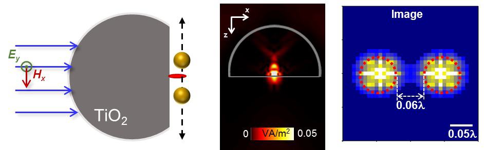
A truncated sphere of titanium dioxide (TiO2) produces a photonic nanojet (PNJ) of electromagnetic radiation (seen in the central plot) that probes two gold spheres. Image credit: Victor Pacheco-Peña.
Ways to break through the diffraction limit and into the regime of subwavelength imaging have been growing ever-more creative. One tool that has proven useful in this endeavour is the photonic nanojet (PNJ) – an extremely narrow and intense beam of radiation at the interface between a dielectric particle and its surrounding medium. Now, a pair of researchers have developed a way to simultaneously minimize the particles and enhance the PNJs, which could benefit many imaging, microscopy and sensing applications, offering a resolution five times better than that of traditional PNJ imaging systems.
Victor Pacheco-Peña from Newcastle University, UK, and Miguel Beruete from the Public University of Navarra in Spain conducted numerical simulations of titanium dioxide (TiO2) particles surrounded by air. The material was chosen specifically for its very high refractive index (around 9.95) and low absorption when excited with 50 GHz radiation, as used in these simulations. This is the key to the success of the study – traditional PNJs are produced in particles that have a lower index (around 2) and must be around five times larger than the wavelength. Thanks to the higher index of TiO2 the particles studied by Pacheco-Peña and Beruete are just over half a wavelength across, bringing the technology to the mesoscale.
Freeing the nanojet
The first dielectric particle tested was an infinitely long cylinder. Initial results showed that a PNJ was indeed produced when the cylinder was illuminated from one side with a plane wave. However it was trapped inside the cylinder, as opposed to resting on the surface as in lower-index particles.
In order to release the PNJ from its dielectric prison, the researchers applied the Weierstrass formula, normally used in the design of solid immersion lenses, to find the distance from the centre at which the cylinder should be truncated. Simulations show that the PNJ at the cylinder’s surface enhances the power of the backscattered signal by a factor of 2.5, with a full-width at half-maximum (FWHM) of 0.14 times the wavelength.
For the second shape, Pacheco-Peña and Beruete studied something a little easier to realise experimentally; a truncated dielectric sphere with equivalent dimensions to that of the cylinder. When illuminated by a plane wave incident on the curved side, a PNJ appears at the flat face of the truncated sphere that is even narrower (FWHM of 0.06 times the wavelength) but slightly less intense (power enhancement of 1.8) than that produced by the truncated cylinder.
Soaring past the diffraction limit
The two researchers involved in this study. Photo credits: Public University of Navarra; Victor Pacheco-Pena
Next the researchers investigated the ability of the PNJs to capture an image with subwavelength resolution. In another numerical model, two small gold spheres are positioned under a truncated dielectric sphere, and the backscattered signal measured from the combined system. The gold spheres are scanned around, which produces an image similar to that from a scanning probe microscope. After testing gold spheres with various separations, the researchers found that they could clearly distinguish spheres with separations as little as 0.06 times the wavelength, a resolution 5 times better than that of traditional PNJ imaging systems.
This study shows a promising future for PNJs in subwavelength imaging and sensing systems. The researchers are currently delving more deeply into other possible geometries for high-index particles, such as cubes and ellipsoids. Perhaps they can beat their own resolution record!
Think small, win big. That’s the mindset that Harvard University’s Laboratory for Integrated Science and Engineering (LISE) has, for a decade and more, tried to encourage by providing a focal point for cross-disciplinary collaboration in nanoscale science and technology. Underpinning that collective endeavour, and housed across three basement floors of the LISE building, is a suite of ultralow-vibration (ULV) facilities for scanning probe microscopy (SPM) – the engine-room, in every sense, of research breakthroughs spanning areas as diverse as high-temperature superconductivity, topological materials and advanced heterostructures.
Joseph Gibbons, principal at Wilson HGA, a Boston-based firm of architects specializing in science and technology facilities for academic and corporate clients, has been instrumental in developing LISE’s ULV capabilities, describing each new ULV lab as “a better version of the one that went before”. Here he talks to Physics World about Wilson HGA’s role in the design and commissioning of the latest ULV facility at LISE, as well as the complexities of research spaces for the study and control of exotic materials at the nanoscale.
Why are “quiet” environments so important for SPM?
It’s primarily a matter of resolution. By minimizing noise and vibration in the laboratory, scientists are able to push their SPM tools to the resolution limit, with that steady environment also enabling long-duration measurements – sometimes as long as several weeks. Unfortunately, many SPM facilities are located on metropolitan campuses with all manner of background noise from trains, subways, buses and trucks. My role as an architect is to counter these noise sources, while taking any inherent noise from the building – for example, due to elevators and air-conditioning units – out of the equation.
How do you create those stable lab conditions over the long term?
While ULV facilities have been around for decades, there are multiple schools of thought on the optimum relationship between the SPM and the base building. For the new ULV facility at LISE, we took vibration and acoustic measurements throughout the building during the initial design phase to identify sources that were eventually making their way into the lab.
From here, we designed backwards by setting benchmarking goals for a range of parameters such as resonance frequency of the plinth (the mass-inertia block on which the microscope sits), vertical natural frequencies, acoustic mitigation through redundant enclosures, and the prevention and control of infrasound (low-frequency sound at less than 20 Hz). Crucially, we were also willing to ditch design based on precedent and subjective paradigm in favour of “out-of-the-box” thinking.
In terms of the specifics, what does that out-of-the-box thinking look like?
Our design approach is based around three main goals. First, isolate the base building from the SPM plinth. Second, isolate the base building from the acoustic enclosure (the environment surrounding the plinth). And finally, isolate the plinth from the acoustic enclosure. This is a unique approach in that we have isolated the plinth from the acoustic enclosure, and both of these are isolated separately from the building in a kind of “Russian doll” configuration.
Splendid isolation: the formwork for the plinth, into which concrete is poured and set (left). When installed, the SPM mounting tripod will sit on top of the large section of the composite cylindrical plinth (right). (Credit: Wilson HGA)
What approach are you using for isolation of the various building blocks of the lab?
Following requirements-gathering discussions with the scientific team, we selected passive isolation for this project, though there is still the option for active cancellation at the SPM instrument itself. Passive isolation depends on mass and, generally, higher mass yields higher performance. Our isolation set-up is completely passive, using pneumatic air springs and natural rubber.
What does that mean for active isolation?
We figure if we can get all of the ambient noise down below 1 Hz in the horizontal and vertical directions, any active isolation at the actual SPM instrument will not need to work very hard. Such active systems require low-voltage signaling between piezoelectrics which, whenever they feel a vibration, automatically generate a vibration of equal and opposite magnitude.
Designing lab space for cutting-edge materials research is an unusual niche for an architect. What attracted you to this specialism?
My background is in the fine arts and architecture, though there are parallels between the sciences and the work we do here at Wilson HGA. In architecture, for example, there’s always a problem that we’re trying to solve, or a thesis that we’re testing, in the course of the design process. That’s the same whether we’re designing a lab or an entire campus.
The secret in every case is to understand the end-user’s requirements for what constitutes an optimum operating environment for a given piece of kit. Often the things we focus on are never thought of by the scientists – for example, how to connect a vacuum pump or electrical supply into an isolated chamber.
The quest for quiet
The latest ULV facility in Harvard’s LISE building is the result of extensive consultation between Wilson HGA and senior researchers. Key features of the project are summarized below.
Double-height below-grade facility: materials of the existing facility include a mix of cast-in-place concrete and fully grouted concrete-masonry-unit (CMU) construction. The existing facility was lined with a redundant fully grouted CMU partition to form the first acoustic barrier.
Acoustic enclosure: this comprises cast-in-place concrete and a customized aluminium structured acoustic partition system. Concrete was used to lower the centre of gravity for the entire assembly and to increase mass. The assembly is isolated from the base building by natural rubber isolation pads.
Service feeds: there are no services permanently installed within the acoustic chamber, ensuring an environment that is completely decoupled from the base-building noise. A series of vibration/acoustic-isolated service feedthrough panels were designed within the concrete section of the chamber base and the adjacent concrete partitions. Services include electricity, signal wire, compressed gas, helium recovery and high/ultrahigh vacuum. There’s also a sample-transfer hatch for the connection of a molecular-beam epitaxy (MBE) chamber with the SPM.
Cylindrical SPM plinth: the composite cylindrical plinth (a cast-in-place concrete mass-inertia block) was designed specifically for this application. The set-up comprises two cylinders: a large-diameter but short cylinder on top of a small diameter but tall cylinder (not unlike an upside-down top hat). Cylinders were chosen for their naturally high resonance frequency and unique flexural modes with respect to the face of the adjacent acoustic enclosure. The lower portion is suspended from the upper, while the entire plinth floats on a pneumatic isolation system. When installed, the SPM mounting tripod will sit on top of the large section, while a hole in the plinth enables routine maintenance.
When western shovel-nosed snakes slither swiftly through mixed terrain, they respond passively to obstacles without neural input. That is the surprising conclusion of Daniel Goldman and colleagues at the Georgia Institute of Technology in the US. What is more, the paths taken by the reptiles bear more than a passing resemblance to the trajectories of quantum particles. The team believes that the snake’s mechanical response to obstacles could inspire new types of limbless robots that could traverse complex environments.
“Modern robots are fantastic if the environment is really simple, but when complex, like in the real terrestrial world with branches, leaf litter and sand, then robot performance degrades very quickly,” explains, Goldman who heads up the Complex Rheology And Biomechanics (CRAB) lab.
Snakes are capable of slithering through and over an amazing variety of terrain, making them particularly interesting animals to mimic. “If we can incorporate some of the principles by which living systems control limbless bodies, it could one day give robots the ability to go anywhere in the terrestrial world,” said Goldman.
Do the locomotion
In previous work, CRAB lab’s Jennifer Rieser discovered that when a snake-like robot (moving with a simple wave pattern) collided with an obstacle it interacted persistently until it pushed past and moved off at an angle to its initial trajectory. Rieser measured a predictable scattering pattern, and then teamed-up with Perrin Schiebel to investigate whether the same locomotion dynamics were found in real snakes.
Limbless animals have complex dynamics – they can bend and twist in all directions to take a myriad of shapes – and understanding this complexity can be very difficult. So Rieser and Schiebel simplified matters by focussing on the western shovel-nosed snake, which uses relatively simple head-to-tail waves to slink swiftly over the desert sands at night.
Using eight blindfolded snakes, they placed one creature at a time into a carpeted arena with a 1D lattice of dowel posts (see figure). A high-speed camera was used to track the snakes as they performed 253 manoeuvres through the lattice.
“When we put the snakes down in the arena, they started moving using the same waveform they use on desert sand,” explains Schiebel. “They would then encounter the dowel grating, pass through it, and continue on the other side still using that waveform.”
Snake diffraction
The first and most unusual observation the physicists made was that the overall pattern of how the snakes emerged from the lattice was very similar to how photons interact with a diffraction grating.
Goldman was surprised to see this and explains, “In the quantum world you see individual particles interacting with a regular array and emerging in preferred angles, but I didn’t expect to see such phenomena when working on animals and robot”.
Biomechanics expert Noah Cowan at Johns Hopkins University told Physics World that this connection is “striking” adding, “It has a remarkably similar diffraction pattern to a photon diffraction grating”. Indeed, Goldman is keen to discover whether the diffraction of sub-atomic particles can be mimicked and investigated using snakes.
Passive dynamics
Although the live snakes move much faster through the lattice than Rieser’s robots, their scattering patterns are very similar. This suggests that the navigation-control system used by the snakes resembles that used by the robots – an “open-loop system” that lacks sensory feedback and response.
“When the desert snakes scatter they are moving so fast we don’t think the nervous system can correct for the perturbations,” said Goldman. “And based on the diffraction pattern and force pattern generated on the array, the snakes appear to maintain this motor programme and close a feedback loop when they are in the lattice.”
To further corroborate this open-loop, purely passive mechanical response, the CRAB lab team modelled geometric snake muscle dynamics with open-loop controls, and found it to closely match the experimental snake scattering pattern.
Muscular Robotics?
Biorobotics specialist Auke Ijspeert of the Swiss Federal Institute of Technology at Lausanne, praised the teams application of physics to robotics. “The core message is that when you design a robot it’s important to think about imbedding these interesting biomechanical features,” said Ijspeert.
Cowan agrees that applying these features could help a limbless robot interact more robustly with complex environments. He comments, “I think it’s another signpost underscoring that locomotor ability is not going to be solved by artificial intelligence alone.”
The CRAB lab members are keen to test this concept by applying snake-like muscles to their robot and testing it within a complex environment.
Spider dragline silk exhibits a unique self-powered actuation, controlled simply by tuning relative humidity, according to scientists. A team from China, the UK and USA have shown that high humidity can bring about a huge twist deformation in the silk fibres. This opens up an extensive range of possibilities for its potential use as a rotary actuator. It is also particularly interesting for applications such as artificial muscles.
Spider dragline silk is tougher than nearly all synthetic fibres, also possessing high elasticity, thermal conductivity and interesting torsional behaviour. In addition, it is sensitive to water, exhibiting the phenomenon of supercontraction, where water disrupts the hydrogen bonds crucial for its structure, increasing molecular mobility and allowing structural rearrangement. This leads to a radical shrinking and swelling of the dragline silk. Until now, however, little was known about how water affects its torsional behaviour.
Published in Science Advances, the group led by Dabiao Liu at Huazhong University of Science and Technology and Markus Buehler at MIT have discovered an impressive humidity-induced twist deformation of dragline silk. By taking steps to understand this at the molecular level, they are pinning down the connection between the structural characteristics of the material and its unique humidity-driven torsional behaviour.
Precise control
The group demonstrated that applying stepwise changes in humidity caused the silk to immediately twist above a certain threshold, which varies only slightly with the species of spider. Whereas human hair or Kevlar fibres barely show the slightest traces of twisting, the torsional response of dragline silk is impressive: as soon as humidity reaches about 70%, this can generate a huge twist of up to 300 °/mm in the silk. This is thousands of times greater than actuators based on shape-memory alloys or conducting polymers. The silks showed rotation comparable to or even greater than artificial “muscles” made up of carbon nanotubes and powered by electricity.
The team show that the dragline silks are also responsive to cyclical changes in humidity by repeatedly changing relative humidity from 40 to 100% and back to 40%. When humidity is below the threshold level the silk remained still, but reaching the threshold immediately triggered the twisting behaviour. From this, the group demonstrated the sensitivity of the response, highlighting the possibility of using humidity as a precise control for twist deformation.
A molecular level twist
To understand the structural changes responsible for this torsional behaviour and the underlying mechanism, the team used molecular simulations of two major proteins found in the silk. They showed that the torsional behaviour can be attributed to the prevalence of one specific amino acid, proline, in one of these proteins. This amino acid can force the molecule into a twisted pattern, as well as giving rise to the torsional properties by disrupting hydrogen bonding in the molecule. The group suggest that humidity can induce this proline twisting, which then turns the dragline silk, acting as a torsional actuator.
By generating such a huge deformation without any mechanical input, this self-powered actuation driven by humidity can lead to exciting applications such as hydroscopic artificial muscles. It even opens up the possibility of humidity-driven soft robots or smart textiles.
Subcortical brain structures such as the thalamus and nucleus accumbens play a critical role in controlling motor, emotional and associative activity. Dysfunction in communication between these structures and with the cortex can lead to serious diseases, including Tourette syndrome, obsessive-compulsive disorders (OCD) and Parkinson’s disease. However, it is extremely difficult to study these structures, which are located deep inside the brain, and it’s not precisely clear how they work.
Current treatments for these diseases are based on deep brain stimulation (DBS), an invasive approach that uses electrodes implanted into the centre of the brain. DBS has been shown to be effective in Parkinson’s, but doesn’t work so well for OCD and Tourette’s. Understanding how subcortical brain zones function and communicate could help improve treatments, but existing approaches for measuring activity in deep brain areas are also highly invasive.
As such, researchers from the University of Geneva (UNIGE) and Cologne University investigated whether electroencephalography (EEG) — a non-invasive method that records the brain’s electrical activity via electrodes placed on the scalp — could measure deep brain activity from outside the skull. They demonstrated, for the first time, that EEG combined with mathematical algorithms can record signals usually only seen by implanted electrodes (Nature Communications 10.1038/s41467-019-08725-w).
Simultaneous measurement
To determine whether activity in deep brain structures can be sensed using EEG, the researchers simultaneously recorded subcortical activity using the implanted electrodes and high-density (256-channel) EEG scalp electrodes. They examined two patients suffering from Tourette’s and two OCD patients, who had DBS electrodes implanted in the thalamus and nucleus accumbens, respectively.
The results from the two measurement techniques correlated perfectly. “The mathematical algorithms that we developed meant we could accurately interpret the data provided by the EEG and ascertain where the brain activity was coming from,” explains first author Martin Seeber.
“In obtaining highly similar signals as with the implants, we finally proved that surface EEG can be used to see what is happening in the deepest part of the brain without having to go into it directly,” adds senior author Christoph Michel.
The authors note that previous work using simulations and source reconstruction provided indirect evidence for the detectability of subcortical sources in EEG recordings. “In this work, we can confirm this finding with direct evidence from intracranial recordings providing the ground truth of subcortical signals, in combination with non-invasive EEG source reconstruction locating these signals in close proximity to the actual recording sites,” they write.
With this confirmation, the researchers can now try to understand how subcortical structures communicate with each other and with the cortex, hopefully leading to increased understanding of the causes of diseases such as Tourette’s and OCD. The team is also keen to use the technique to improve existing treatment methods, based on rebalancing network interactions using a very slight electric shock. They would also like to address other disorders, such as obesity, addiction or Alzheimer’s disease.
“Lastly, we hope that in time we’ll be able to stimulate the deep brain areas from the surface via an electromagnetic treatment, doing away with electrode implants in the brain once and for all,” says Michel.
Theory and experiment. They are the two pillars of science that for centuries have underpinned our understanding of the world around us. We make measurements and observations, which we then link to theories that describe, explain and predict natural phenomena. The constant interplay of theory and experiment, which allows theories to be confirmed, refined and sometimes even overturned, lies at the heart of the traditional scientific method.
Take gravity. At the start of the 20th century, Newton’s law of universal gravitation had stood the test of time for over 200 years, but it could not explain the perihelion precession of Mercury’s orbit, which was slightly off what Newtonian gravity predicted. Different ideas were proposed to explain this blot on Newton’s otherwise spotless copybook, but they were all rejected based on other observations. It took Einstein’s general theory of relativity – which revolutionized how we perceive time, space, matter and gravity – to finally explain the tiny disagreement between the predictions from Newton’s theory and observations.
Even now, a century later, Einstein’s theory continues to be poked and prodded for signs of weakness. The difference today is that these tests are not necessarily based solely on experiments or observations. Instead, they often rely on computer simulations.
New views of the world
For more than half a century, computational science has expanded scientists’ toolkit to go far beyond what we could hope to observe with our limited vision and short lifespans. In the case of relativity, astrophysicists can now build entire simulated universes based on different modifications to relativity. Powerful computers and clever codes let researchers alter the initial physical conditions in the model, which can be run automatically from soon after the Big Bang to today and beyond.
“Computation fills in a gap between theory and experiment,” says David Ham, a computational scientist at Imperial College London in the UK. “A computation tells you what the consequences of your theory are, which facilitates experimentation and observation work because you can tell what you are supposed to look for to judge whether your theory is valid.”
Computation is not just an extra tool. It is a new way of doing science, irrevocably changing how scientists learn, experiment and theorize
But computation is not just an extra tool. It is a new way of doing science, irrevocably changing how scientists learn, experiment and theorize. In her 2009 book Simulation and its Discontents, Sherry Turkle – a sociologist of science from the Massachusetts Institute of Technology in the US – outlined some of the anxieties that scientists had from the 1980s to the 2000s over the growing pervasiveness of computation and how it was changing the nature of scientific inquiry. She summarized them as “the enduring tension between doing and doubting”, pointing to a worry that younger researchers had become “drunk with code”. So immersed were they in what they created on screen, they could no longer doubt whether their simulations truly reflected reality.
However, Matt Spencer, an anthropologist from the University of Warwick in the UK, believes that science and scientists have evolved in the decade since Turkle’s book was published. “I don’t think you’ll hear this kind of opinion that much in physics these days,” says Spencer, who studies computational practices in science. Indeed, he points to many natural phenomena – such as the behaviour of whole oceans – that simply cannot be manipulated on an experimental scale. “Through exploring a vastly greater range of possible states and processes with simulations, there may be better ways to truly understand underlying physics with simulations,” he says.
Ham agrees, noting that physicists have had to accept they will never be able to understand everything about a simulation. “It’s an inevitable consequence of the systems we study and the techniques we use getting bigger and more complicated,” he says. “The proportion of physicists who actually understand what a compiler does, for example, is vanishingly small – but that’s fine because we have a mechanism for making that OK, and it’s called maths.”
Although most physicists now view computation and simulation as an essential part of their work, many are still coming to terms with the disruption caused by this third pillar of science, with one of the biggest challenges being how to verify the increasingly complex codes they produce. How can researchers, in other words, be confident their results are correct, when they don’t know if their code does what they think it does? The problem is that while programming is widely taught in undergraduate and graduate physics courses, code verification is not.
Ham voices another concern. “Something that absolutely is the enemy of progress is the ‘not-invented-here’ syndrome,” he says, referring to the belief – particularly in smaller research groups – that it is cheaper, better and faster to develop code in house than bring it in from elsewhere. “It’s a recipe for postdocs spending most of their science time badly reinventing the wheel,” Ham warns.
With limited budgets to explore better methods, Ham says that researchers often find themselves using code that “doesn’t even work very well for them”. So to help these teams out, Ham and colleagues at Imperial in the Firedrake project are building compilers that take the maths of a given problem from the scientists and then automatically generate the code to solve it. “We’re effectively separating out what they would like numerically to happen from how it happens,” he says.
For physicists who do develop code that fits their purpose well, it’s tempting to use it to solve other scientific questions. But this can lead to further problems. In 2015 Spencer published an account of 18 months he spent observing a group of researchers at Imperial, in which he explored their relationship with a software toolkit called Fluidity. Developed in the UK in around 1990, Fluidity started out as a small-scale fluid-dynamics program to solve problems related to safely transporting radioactive materials for nuclear reactors. But its elegance and utility were soon recognized as having potential in other fields too.
The Imperial group therefore started building new functions on top of Fluidity to serve more researchers and solve further problems in geophysics, ranging from oceans, coasts and rivers to the Earth’s atmosphere and mantle. “Scientific discovery often takes opportunistic pathways of investigation,” says Spencer. “Because Fluidity grew in complexity in this organic way, without foresight of how extensive it would eventually become, problems did accumulate that over time made it harder to use.”
Keeping the code flexible, readable and easy to debug eventually became a serious challenge for the researchers, to the point where one member of the Fluidity team complained that “there were so many hidden assumptions in the code that as soon as you change one detail the whole thing breaks down”.
The team responded by investing in a rewrite of Fluidity, reimplementing the algorithms using best practice software architecture. Yet growing software is not just a technical challenge; it is also a social one. “We could think about the transition to the new Fluidity as crossing into something more akin to ‘big science’,” says Spencer. “Large-scale collaboration often has to be more bureaucratically managed, and this of course is a fresh source of tension and negotiation for researchers.”
Code that can grow
One large software project that has considered the inherent problems with extending code and collaboration from the outset is AMUSE. Short for the Astrophysical Software Environment, it’s a free, open-source software framework developed over more than a decade, in which existing astrophysics codes – modelling stellar dynamics, stellar evolution, hydrodynamics and radiative transfer – can be used simultaneously to explore deeper questions.
Like LEGO bricks, AMUSE is made up of individual codes, each of which can be added or taken away as required to create a new simulation. Managed by a core team led by Simon Portegies Zwart at Leiden Observatory in the Netherlands, the design allows researchers to change the physics and algorithms without affecting the global framework. AMUSE can therefore evolve while keeping the underlying structure solid.
Yet even AMUSE faces challenges. Portegies Zwart sees funding for basic software maintenance and development as the greatest threat to AMUSE and the next generation of large-scale simulations. “Compilers change, operating systems change, and the underlying codes eventually need to be updated,” he says. “It’s relatively easy to acquire funding to start a new project or to write a new code, but almost impossible if you want to update or improve an existing tool, regardless of how many people use it.”
It’s relatively easy to acquire funding to start a new project or to write new code, but almost impossible if you want to update or improve an existing tool
Expert support
So where does all this leave us? We stand at a point where theoretical calculations coupled with laboratory experiments are often not enough to deal with the complex physics questions researchers are trying to address. Even then, simulating this physics is usually beyond the coding skills of a solo scientist or even a group of scientists. As a result, computations and simulations are increasingly being developed in collaboration with expert coders who have very different and complementary skills.
To keep up the pace of scientific progress, many computational scientists feel that funders need to fully recognize that our third pillar of science must support all of these experts. If they don’t, those who maintain and develop collaborative large-scale physics code bases could start looking to take their careers elsewhere. After all, they have many valuable and marketable skills. “There are,” Ham warns, “plenty of non-science jobs out there for them.”
Most icebergs look white or blue but since the early 1900s sailors have reported seeing dark green icebergs off some parts of Antarctica. And residents of Davis and Mawson stations, on opposite sides of Prydz Bay in East Antarctica, commonly see “jade bergs”. Now scientists may have identified the cause of the strange colouration – iron oxides from rock dust.
Icebergs result when large chunks of ice break off into the ocean from the ends of glaciers or ice shelves. As well as snow, and ice formed from compacted snow, icebergs calved from floating ice shelves may contain marine ice – ocean water frozen onto the bottom of the shelf in a layer that can be 100 m thick. It’s this marine ice that sometimes appears green; if it reaches the edge of the shelf without melting and breaks off as part of an iceberg that later tips over, it will be visible to passing sailors and researchers.
Sea water sometimes freezes to the underside of ice shelves, creating a layer of what’s called marine ice. (Credit: AGU)
An early candidate for producing the green colour was dissolved organic carbon but later measurements showed similar levels of this carbon in both green and blue marine ice.
Rocky start
Stephen Warren of the University of Washington, US, and colleagues turned their thoughts to iron oxides following the discovery of large amounts of iron in East Antarctica’s Amery Ice Shelf.
Erosion turns iron-based rocks at the base of the ice sheet into “glacial flour”, the theory goes. Particles of this flour enter the water and nucleate ice crystals that float upwards, collecting more particles en route, to form a layer of green marine ice underneath the floating ice shelf.
But why is that ice green? If it doesn’t contain air bubbles, ice appears blue because it preferentially absorbs red wavelengths. Air bubbles, as found in the glacier ice formed from compacted snow, reduce this absorption by refracting light and scattering it out of the material. This clouds and whitens the ice’s appearance.
Researchers on top of a large composite iceberg in October 1996. (Credit: Collin Roesler)
Marine ice, though, tends not to contain air as it forms under pressure several hundred metres beneath the ocean, where air is more soluble in water. In the absence of iron oxide, this marine ice appears clear and blue.
Add iron oxide particles to the mix and the marine ice’s natural blue combined with the red or yellow introduced by the mineral shifts the ice to absorb least light at green wavelengths. The result is an emerald green colour.
Warren began studying green icebergs in 1988, when he took a core from one example of the phenomenon near the Amery Ice Shelf.
“When we climbed up on that iceberg, the most amazing thing was actually not the colour but rather the clarity,” says Warren. “This ice had no bubbles. It was obvious that it was not ordinary glacier ice.”
Eat your greens
What’s more the iron in the icebergs may be playing a role in the wider ecosystem.
“We always thought green icebergs were just an exotic curiosity, but now we think they may actually be important,” says Warren. “The iceberg can deliver this iron out into the ocean far away, and then melt and deliver it to the phytoplankton that can use it as a nutrient. It’s like taking a package to the post office.”
Warren and colleagues from Bowdoin College, University at Albany, and State University of New York, all in the US, and the Australian Antarctic Division reported their work in Journal of Geophysical Research Oceans.
Particle physicists have expressed their disappointment after the Japanese government today failed to announce its intention to host the ¥800bn ($7.5bn) International Linear Collider (ILC). Officials in Japan said that their government has formally “expressed an interest” in the 20 km-long particle smasher but has not decided whether to host the machine. The final go-ahead will only be given if enough international support and funding can be found to construct the machine and there is a consensus within the Japanese scientific community that the project is worth pursuing.
First mooted over a decade ago, the ILC would accelerate and smash together electrons with positrons to study the Higgs boson and other particles in precise detail. The ILC’s five-volume technical design report was published in June 2013, in which it called for a 30 km-long linear collider that operating at around 500 GeV (see timeline below). The Japanese physics community quickly got behind the project, expressing its desire to host the machine, with a site in the Tōhoku region, about 400 km north of Tokyo, chosen as a potential location.
However, the government has dragged its feet over whether to support the ILC and in 2017 physicists came up with a revised plan to make it more palatable. This involved reducing the ILC’s energy to 250 GeV — an energy aimed to study the 125 GeV Higgs boson — and shortening the length of the tunnel to around 20 km, with the option of later upgrading the collider to energies of around 1 TeV. However, their plans were hit late last year when an independent committee of the Science Council of Japan (SCJ) issued a report that failed to support the ILC’s construction in Japan. The SCJ pointed out that the ILC did not yet have enough international backing, stating that the collider’s importance beyond research was “unclear” and “considered to be limited”.
Setting conditions
Given that European particle physicists are currently updating their future strategy, which is due out by May 2020, officials then gave the government a deadline of March to decide on whether to support the ILC in Japan. Today’s announcement means that government agrees with the Japanese particle physics community that the ILC is worth pursuing and that it will enter negotiations to host the machine. However, it will only give the ILC the final go-ahead if those negotiations are successful and if international support, particularly funding, can be found. It is expected that the government could supply half the $7.5bn with the other half needing to come from international partners such as the US, CERN and Europe as well as Canada.
Timeline: twists and turns of a linear accelerator
2004 An international panel of experts decide that a future linear collider should be based on superconducting technology that has been developed at the DESY laboratory in Germany
2005 Barry Barish of the California Institute of Technology in the US is chosen to lead the effort to build the International Linear Collider (ILC). The ILC’s first tentative design is released calling for a 20 km-long machine that would operate at 500 GeV with a possible future upgrade to 1 TeV that would require extending the tunnel by an additional 18.6 km
2007 Updated “reference design” is released for the ILC calling for two 12 km-long arms to collide electrons with positrons. The estimated cost of the ILC is $6.7bn
2011 The Japanese particle-physics community announces it will bid to host the ILC with possible candidate sites in Kyushu and Iwate
2013 Lyn Evans, who masterminded the Large Hadron Collider’s construction, takes up the reins as linear-collider director, overlooking the design of the ILC. The “technical design report” for the ILC is released calling for a 31 km-long track of superconducting cavities that accelerate electrons to 500 GeV. The ILC community identifies a location in the Iwate prefecture north of Tokyo as a possible site for the ILC
2016 Japan’s High Energy Accelerator Research Organization (KEK) releases a 12-page plan showing that they have measures in place if the Japanese government decides to begin negotiations with other countries to start construction
2017 The International Committee for Future Accelerators, which oversees work on the ILC, endorses plans to reduce the scope of the collider. Estimated to cost $7.5bn, the ILC would be built in a 20 km-long tunnel and with an initial design energy to 250 GeV with the option of further energy upgrades
2018 A report by the influential Science Council of Japan raises several issues about the Japan hosting the ILC and does not support its construction.
Another condition laid out by the government is that the ILC needs to be more widely supported by the Japanese scientific community. That means that it will need to complete the necessary procedures to be included in the next roadmap of large science projects put together by Japan’s Ministry of Education, Culture, Sports, Science and Technology. Physics projects included in MEXT’s 2017 roadmap included the Hyper Kamiokande neutrino detector as well a high luminosity upgrade for the Large Hadron Collider. The government also said that the ILC must be included in the SCJ’s master plan of large-scale projects, which will not reach a conclusion until October this year.
“It is actually extremely positive that the Japanese government says that it has an interest in the ILC project,” Hitoshi Murayama from the Kavli Institute for the Mathematics and Physics of the Universe in Tokyo told Physics World, adding that to make such a statement meant that discussions must have taken place with other government ministries including the finance ministry.
This is a real window of opportunity for Japan, but this window cannot remain open for much longer
Philip Burrows
Speaking at a press conference this morning in Tokyo organised by the International Committee for Future Accelerators (ICFA), which oversees work on both the ILC and a rival design the Compact Linear Collider, ICFA chair Geoffrey Taylor noted that that they have been encouraged by the government’s comments. “It shows us the political and executive environment in Japan is rapidly moving towards the ILC,” he says. “The important step we await now is for the government to commit and declare its interest in becoming the host of the ILC.”
Moving on
Yet particle physicist Brian Foster from the University of Oxford, who was European regional director for the ILC’s Global Design Effort, says that he is “disappointed” by the statement. “It is difficult to be convinced that the Japanese government is serious about this,” says Foster. “Delaying the decision in this way seems like a typical Japanese way of saying ‘no'”. Foster adds that it is especially concerning that the Japanese government has now referred the decision process back to the SCJ, which has not been enthusiastic about the ILC. “How all this will now play out in the European strategy discussions is hard to know”. At the press conference, it was noted that negotiations on cost sharing will now be carried out by officials from the KEK particle-physics lab. Yet Foster warns that this is a “waste of time”. “Negotiations needs to take place at a higher level,” he adds.
“It is difficult to be convinced that the Japanese government is serious about this. Delaying the decision in this way seems like a typical Japanese way of saying ‘no’.
Brian Foster
The announcement from the Japanese government is also unlikely to result in linear-collider physicists getting behind the ILC and ditching plans for CLIC, which would offer higher collision energies up to around 3 TeV. “Today’s MEXT statement appears to fall short of a clear positive decision by the Japanese government, and is, frankly, disappointing”, says particle physicist Philip Burrows from the University of Oxford, who is CLIC’s spokesperson. “CLIC represents a serious alternative design for an energy-frontier linear collider and we will make every effort to keep it on the table for consideration pending greater clarity on ILC from the Japanese government. This is a real window of opportunity for Japan, but this window cannot remain open for much longer – the world must move on, other projects are advancing, and CLIC provides a great opportunity for a linear collider Higgs factory in Europe.
That view is shared by particle theorist John Ellis from King’s College London who told Physics World that the statement is “disappointing” for the community. “For the time being, the European particle physics strategy update will have to continue without assuming that the ILC will go ahead,” he says, adding that there are other projects on the table such as CLIC, China’s Circular Electron Positron Collider and the Future Circular Collider that could “do similar physics and provide ways forward for the community”.
International Linear Collider Q&A
What is the International Linear Collider (ILC)?
The ILC is a 20 km-long particle collider that will accelerate electrons and positrons to energies around 250 GeV. To do so, it will consist of thousands of superconducting radiofrequency accelerator cavities made of niobium. The ILC will then smash these beams together roughly 7000 times a second at an “interaction point”. The ILC will have two all-purpose detectors based around the interaction point — SiD and ILD — that would take turns being in the beam. Interchanging the detectors is estimated to take around a day to complete.
How is this different from CERN’s Large Hadron Collider?
The 27 km-circumference LHC is a circular collider that is made up of more conventional technology such as radiofrequency cavities that accelerate the beam, dipole magnets that bend the particles along a circular path, and quadrupole magnets that focus the beam. The ILC instead uses superconducting cavities to accelerate the beam along a straight path before being focussed by quadrupole magnets. This linear acceleration has the advantage that the electrons do not lose energy via X-rays when travelling along a circular path. The benefit of a circular machine is that it allows for more integration points — four in the LHC’s case, with no need to swap detectors.
Has this accelerator technology been tested before?
Yes. The European X-ray Free Electron Laser (E-XFEL) facility near Hamburg, Germany, uses 768 superconducting niobium cavities to accelerate electrons to 17.5 GeV over 1.7 km. Rather than collide the particles, however, the E-XFEL makes them produce X-rays that are then used for a range of experiments from biophysics to condensed-matter physics. The E-XFEL is considered to some extent as an ILC prototype.
What would the ILC study?
Its main aim would be precision studies of the Higgs boson, which was discovered in 2012 at the LHC. The LHC has managed to measure the properties of the Higgs – notably how it couples to other particles – with a precision of around 20%. Yet the LHC’s proton-proton collisions suffer from a large amount of “debris” that affects the precision of the measurements. As electrons and positrons are fundamental particles, their collisions are much “cleaner” meaning that the ILC would improve this precision to 1% or lower. The ILC could also be later upgraded to higher energies to study the top quark.
Why is this exciting?
Physicists hope that the door to “new physics” could be opened through precision studies of particles such as the Higgs. This would come from deviations from those predicated by the Standard Model of particle physics.
Why has Japan dragged its feet for so long?
Japan has balked at the potential cost of building the ILC, which is one reason why physicists proposed a scaled-down version in 2017 that is both cheaper and would not take as long to build.
So why now?
Particle physicists are feverishly planning the next collider following the LHC and the ILC is the most mature proposal. The time is also right given that Europe will update its particle physics strategy next year. A further reason is using the project as part of the reconstruction efforts following the magnitude-9 earthquake and tsunami that hit the Tōhoku region in 2011.
Are we far from a decision?
Who knows. Negotiations will continue with international partners, but if the Japanese government does not receive sufficient support then the ILC could still not go ahead. The coming years will be crucial for the project.
When could the ILC see the light of day?
If everything goes well, 2035 at the earliest. Negotiations and preparations could take around four years to complete with construction then taking a decade.
Arrays of synthetic cell-like capsules, or protocells, made of proteins and polymers can communicate with each other via chemical signals and perform molecular computation thanks to DNA logic gates entrapped inside them. This is the new finding from researchers in The Netherlands and the UK who say that the circuits might serve as molecular biosensors for diagnosing disease or in therapeutics applications, such as to control drug delivery.
DNA computers work using programmable interactions between DNA strands to transform DNA inputs into coded output, explain Stephen Mann of the University of Bristol and Tom de Greef of Eindhoven University of Technology, who led this research effort. These devices operate very slowly, however, since they work in biological environments where they rely on random diffusion to interact with each other and execute a logic operation.
If these DNA strands were assembled inside capsules that could transmit DNA input and output signals to each other, this would increase operating speed. Such encapsulation would also protect the entrapped DNA strands from being degraded by enzymes in blood or serum, for example.
BIO-PC
Mann and de Greef and colleagues have now made such a system using a platform known as “biomolecular implementation of protocellular communication” (BIO-PC). This is a programmable messaging system based on protein microcapsules called proteinosomes containing molecular circuits that can encode and decode chemical messages from short single-stranded nucleic acids.
The proteinosomes are permeable to short single-stranded DNA (containing less than 100 bases), which makes them ideal for protocellular communication, say the researchers. The molecular complexes inside the proteinosomes can work as signal processors, such as logic gates, and contain two different DNA strands tagged with fluorescent labels (so that the researchers can track the activity of the DNA). The proteinosomes themselves are sandwiched between pairs of small pillars in a microfluidic device.
“An incoming DNA strand with the correct sequence can bind with one of the gate’s DNA strands,” explain Mann and de Greef. “This displaces the gate’s other DNA strand. The ejected strand then leaves the protocell and acts as the input signal for a second protocell containing a different gate.”
Towards disease detection
By carefully tailoring the protocells, the DNA gates and the signals transmitted between them, the researchers say they are able to construct a range of different circuits. These include logic gates like AND and OR, and a feedback circuit in which the output strand from one group of protocells deactivates the fluorescent tag in another group. Some protocell circuits can even amplify signals as they transmit them, they explain.
The team, reporting its work in Nature Nanotechnology, says that it is now further developing its DNA circuits into a system that could diagnose disease by detecting tell-tale patterns of microRNAs (which help regulate gene expression). “We’re currently working with Microsoft to build a DNA computer that can do microRNA processing from human blood using this technology,” says de Greef. “I think a DNA computer could eventually do this fully autonomously.
“Microsoft has also been working on storing large quantities of data within DNA using the molecule’s sequence of bases to encode this data, he says. “We hope to integrate this approach with our DNA computing technology.”
Prostate cancer is the most common cancer in men and at later stages of the disease many patients develop painful bone metastases. One promising modality for management of skeletal metastases is targeted radionuclide therapy, in which a radioactive drug travels through the patient’s bloodstream to the tumour where it delivers radiation to cancer cells.
Radium-223, which targets areas of increased bone turnover, has emerged as a key radionuclide for such treatments. The atoms decay via emission of alpha particles that deposit a high amount of energy over a short distance (70–100 μm), damaging the DNA of targeted cells while limiting exposure to healthy tissue.
A large trial (ALSYMPCA) of radium-223 dichloride (223RaCl2) in patients with metastatic prostate cancer bone metastases provided proof that the treatment prolonged the time to a patient’s first symptomatic skeletal event (SSE) and increased overall survival. But questions remain regarding the dosimetry and pharmacodynamics of 223RaCl2.
To investigate the mechanisms of action of 223RaCl2, a team at Queen’s University Belfast has performed mathematical modelling of tumour growth using three different uptake models. To determine the most realistic scenario, they compared the models’ predictions of time to first SSE with published clinical data (J. Radiat. Oncol. Biol. Phys. 10.1016/j.ijrobp.2018.12.015).
Three scenarios
The researchers used the established Gompertz model to simulate tumour growth, and incorporated the effects of 223Ra treatment into the model, based on three biophysical scenarios. First, they considered uniform exposure, which assumes that all tumour cells are equally affected by radiation dose.
“We were surprised how much the uniform model over-estimated the effects of 223Ra treatment, so we knew that less of the tumour must be exposed,” explains co-author Stephen McMahon.
As such, McMahon and colleagues tested two other scenarios: an outer layer effect, where only the surface of the metastatic volume is exposed to radiation; and constant volume exposure, where the number of affected cells remains constant throughout tumour growth.
Schematic showing the tumour volumes exposed (orange) and not exposed (blue) to radiation for the uniform (A), outer layer (B) and constant volume (C) exposure scenarios. (Courtesy: H M R Moreira et al J. Radiat. Oncol. Biol. Phys. 10.1016/j.ijrobp.2018.12.015)
“With suitable dose-rate tuning, we were able to get good agreement for patients who failed at late time-points. This suggested that the uniform model was good for small tumours, but rapidly saturated — and the constant volume model is the simplest approximation of that behaviour,” says McMahon. “The true biology is likely more complex, but this worked well for this initial analysis.”
To test their models, the researchers employed clinical data from the aforementioned 223RaCl2 trial, which included both treated and control groups. They used these data to generate a “virtual patient population” with a range of initial tumour volumes that reproduced the observed time to SSE in the control group.
The researchers then simulated the effects of 223Ra treatment on the virtual population, using each of the three radiation exposure models. To relate tumour growth to SSE, they assumed that skeletal events occurred when the number of tumour cells reached 80% of the total tumour burden that can be supported by the patient.
Clinical comparisons
Using an initial dose rate based on published rates for an average-sized patient, the uniform effect scenario produced over-optimistic results. It gave 12- and 6-month delays in reaching the number of cells corresponding to an SSE, for late and early tumour stages, respectively. Even with a lower initial dose rate, this model overestimated the effects on patients with high disease burden and under-estimated the effects on patients with lower disease burden.
Comparison of treatment and placebo data from the ALSYMPCA trial with the uniform (initial dose rate of 0.0103 Gy/h and best-fit parameters), outer layer and constant volume exposure models. (Courtesy: H M R Moreira et al J. Radiat. Oncol. Biol. Phys. 10.1016/j.ijrobp.2018.12.015)
The outer layer effect scenario predicted cell killing rates that were too high for early tumour growth stages and too low for later tumour growth stages, with poor agreement with clinical data.
The constant volume exposure scenario provided the closest match to the clinical data for patients treated with 223RaCl2. These results suggest that the effects of 223Ra saturate rapidly with tumour volume, only affecting a constant number of cells regardless of tumour growth (once the tumour volume exceeds a certain limit).
The authors conclude that metastatic tumour cells do not experience a uniform dose exposure, with only a sub-population of the tumour affected by 223Ra. This finding is particularly significant since uniform distribution of radionuclide activity in bone metastatic volumes is frequently assumed in conventional dosimetric calculations.
“We were able to show that some common models of 223Ra uptake did not work well to describe the clinical data, and that there was strong evidence of saturation of uptake in even relatively small metastases,” says McMahon. “This represents some of the first biophysical analyses of these data, and the saturating uptake, if verified, may have significant implications for future attempts to optimize drug design and scheduling in radionuclide therapies.”
McMahon notes that the team’s clinical partners are currently completing a trial combining 223Ra treatment with external-beam radiotherapy. “This is an exciting opportunity, as this trial includes detailed molecular and MR imaging, which will enable us to quantify the disease burden and delivered dose to these patients in detail,” he tells Physics World. “This will give us a valuable testing data set to validate the model’s assumptions.”