Precise patient positioning is an essential stage in any radiation treatment, but is particularly critical for particle therapies, which are highly sensitive to range uncertainties. If large tumour motion is expected, fiducial markers can be implanted into the tumour to verify target position prior to each radiotherapy fraction. These markers are generally made of high-atomic number materials to ensure that they are visible in X-ray images. They can, however, cause artefacts on the planning CT and can also induce dose perturbations due to edge-scattering during treatment.
To investigate the latter effect, a research team headed up at the GSI Helmholtz Centre for Heavy Ion Research has evaluated the severity of dose perturbations created by four small commercial markers with different geometries and materials. The team conducted experiments using carbon ion beams with three different energies at the Marburg Ion Therapy Center (Phys. Med. Biol. 10.1088/1361-6560/ab762f).
State-of-the-art detector
Previous studies using simulations and radiochromic film measurements showed that larger fiducials and heavier materials caused greater edge-scattering effects. With film measurements, however, it is difficult to predict exactly where to position the films along the beam axis to find the maximum dose perturbation.
To address this limitation, the GSI team developed a measurement system comprising six MIMOSA28 pixel sensors, CMOS-based detectors with a high spatial resolution. “The collaboration between GSI and the IPHC in Strasbourg was a good opportunity to use a state-of-the-art particle physics detector like the MIMOSA28 for clinical applications,” notes first author Claire-Anne Reidel.
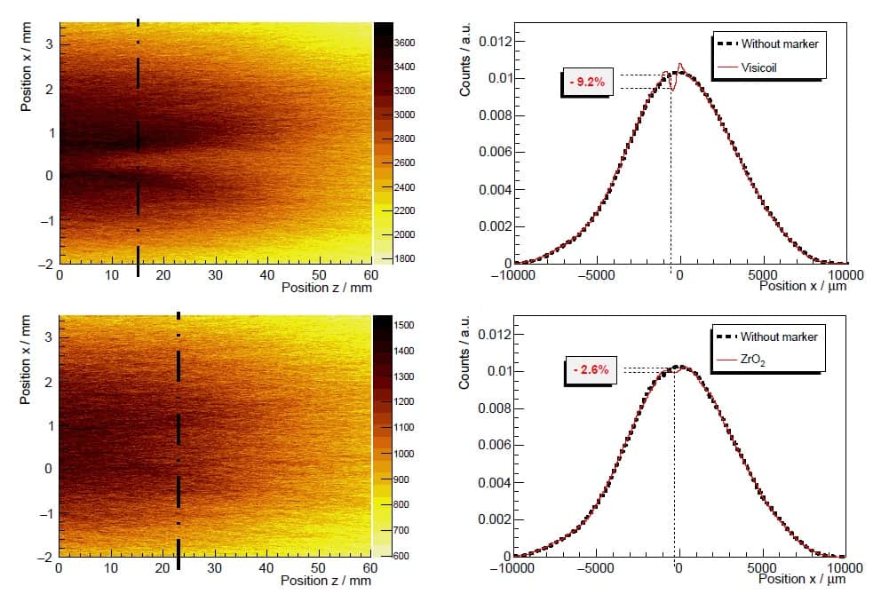
The system measures the trajectory of every particle and reconstructs each individual track, which are then used to generate a 3D fluence distribution. From this, 2D fluence maps can be extracted to determine the position of the maximum dose perturbation along the beam axis. The magnitude of the maximum perturbation is computed by comparing the beam profile at its position with that of a non-disturbed beam.
“In contrast to the use of films, this CMOS technique delivers a continuous fluence distribution (map), where the maximum perturbation can be determined easily and much more information can be extracted than for the films,” Reidel explains.
To validate the tracking system, the team used the MIMOSA28 sensors to measure a 294.97 MeV/u carbon ion beam traversing a small water tank and/or a tissue-simulating polyethylene block. Comparing beam profiles from MIMOSA28 sensors with those measured by radiochromic films revealed good agreement between the two.
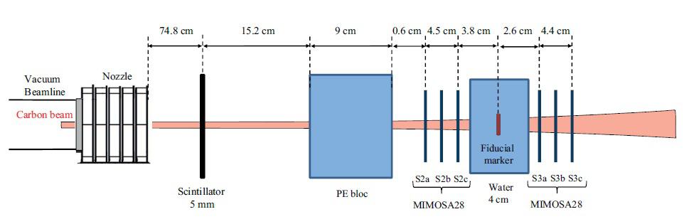
The researchers next benchmarked the MIMOSA28 sensor profiles against films with fiducial markers inserted in the water tank at the beam isocentre. They studied four fiducial markers currently used for image guidance during ion beam therapy, including three small (below 0.5 mm in diameter) gold markers (Visicoil, Gold Anchor #1 and Gold Anchor #2), and a 1-mm diameter carbon-coated ZrO2 marker
The results confirmed the validity of using CMOS sensors for fluence perturbation measurements. For example, beam profiles for a 294.97 MeV/u carbon ion beam with the Gold Anchor #1 in place showed a cold spot of 2.4% measured by the CMOS sensor, and a cold spot of 2.5% measured with the film.
Cold spot comparisons
Reidel and colleagues next used 2D fluence maps to compute the size and position of maximum cold spots generated by the various fiducial markers. They first examined the Gold Anchor #1, Visicoil and carbon-coated ZrO2 fiducial markers at carbon ion beam energies of 278.84, 294.97 and 310.61 MeV/u.
The maximum cold spots and their position downstream of the fiducial marker varied as a function of beam energy, with smaller energies generating greater effects. Markers with higher density and atomic number created stronger and larger cold spots. For example, at 278.84 MeV/u, the maximum cold spots were 2.8%, 6.6% and 9.2% for the ZrO2, Gold Anchor #1 and Visicoil markers, at distances downstream of the fiducial marker of 23, 12 and 15 mm, respectively.
The team also analysed the Gold Anchor #2 marker, which is more complex since it is folded in a random shape. For 310.61 MeV/u carbon ions, the cold spot created by the Gold Anchor #2 was about 4.4%, compared with 4.2% for the Gold Anchor #1 and 7.3% for Visicoil.
Reidel notes that in particle therapy, two opposing fields are typically used per irradiation to minimize the impact of any cold spots, and that treatment fractionation will also smear out any effects. “Cold spots will be a lot more severe in cases where high doses per fraction and a low number of fractions are prescribed or rare treatments using a single-field irradiation,” she adds.
Despite having the thickest diameter, the carbon-coated ZrO2 marker induced lower perturbations (less than 3% for all energies) than gold markers, due to its lower density and atomic number. This could make the ZrO2 marker a preferred candidate for image guidance during carbon ion therapy, though its lower density may make it hard to see on X-ray images.
The researchers conclude that the MIMOSA28 pixel sensors can evaluate fluence perturbations due to edge-scattering effects for small fiducial markers used during ion-beam therapy. They note that the tracker system can determine the maximum cold spots without knowing their position along the beam axis in advance, providing a distinct advantage over radiochromic film.
“In the future, these measurements could be performed with different ion beams, such as protons – which should be more sensitive to perturbations by the markers – or helium beams, and with a more human-like phantom,” says Reidel.