When a spacecraft launches, it uses roughly 75–90% of its propellant getting into orbit. The remaining fraction determines how long it can remain up there, but gauging how much fuel is left in the tank is no easy task in zero gravity. Researchers at the US National Institute of Standards and Technology have now developed a solution based on a suite of sensors that detects the capacitance of liquid inside a spacecraft’s fuel tank and uses these data to reconstruct a three-dimensional picture of the remaining fuel. According to the team, the prototype design could enable satellites to operate for longer, while also helping to avoid damaging end-of-life collisions.
Under zero-gravity conditions, liquid propellants adhere to the inside of fuel tank walls due to surface tension and capillary effects. This unpredictable spatial distribution makes fuel levels hard to determine. Propellants are also free to slosh about, float and form bubbles – none of which happens on Earth.
Several techniques have been developed to measure onboard spacecraft propellant. One of the most common, known as the bookkeeping technique, involves estimating how much is burned with each thrust and subtracting this from the volume of fuel left in the tank. However, while this method is highly accurate at the beginning of a mission, the error of each estimate carries over to the next and accumulates with each thrust, explains team member Nick Dagalakis, a mechanical engineer. “By the time a tank is low, the estimates become more like rough guesses and can miss the mark by as much as 10%,” he says.
Without reliable fuel measurements, satellite operators are in a bind, Dagalakis adds. Retiring a satellite when it still has plenty of fuel left is a waste of money, but letting the tank run dry could leave the satellite stranded, with no fuel left to evade other craft or move to a safe orbit.
An array of capacitance sensors
The new fuel gauge, which was developed by NASA technology transfer manager Manohar Deshpande, relies on a 3D imaging technique called electrical capacitance volume tomography (ECVT). Tomography in general is a way of imaging the internal structure of an object without damaging it; familiar examples include the magnetic resonance imaging (MRI), positron emission tomography (PET) and X-ray tomography routinely employed in hospitals.
ECVT is a more recent variant, and it uses an array of sensors that emit electromagnetic waves. These waves can be detected by the other sensors in the array, and how well they are transmitted depends on the capacitance of whatever lies between the sensors. If there is nothing there, transmission will be high. However, if an object is present, transmission will drop since the object will absorb some of the electromagnetic waves. By placing these sensors around a container, and measuring the signal at many locations, it is therefore possible to build up a 3D picture of the objects inside the container.
Sensor fabrication
To make their ECVT sensors, Dagalakis and colleagues used soft lithography to print wax-coated solid inks onto paper-thin laminated copper sheets. They then etched the copper strips to remove the inks and form the patterns of the sensors and their electrical connections.
Dagalakis notes that because the sensors can be made using well-known MEMS fabrication techniques, the dimensions of the electro-capacitance plate arrays, their gaps and shielding strips can be set with a high degree of accuracy. These fabrication techniques also eliminate the need to solder electrical wires on the plates and strips and route wires through the sensor arrays and tank structures. Finally, since the strips are flexible, they can be applied to the interior of an egg-shaped vessel – like a spacecraft fuel tank.
3D image of fuel content
Many liquid propellants (including liquid hydrogen and hydrazine) are highly flammable in the Earth’s atmosphere. As a safer alternative, the researchers tested their sensor array using a fuel substitute that has a dielectric constant similar to that of real spacecraft propellant but is stable in air.
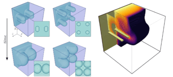
The researchers placed their sensors around a test tank (a miniature version of a real NASA fuel tank) and measured the difference in transmission of every possible sensor pair in their array. By combining these measurements, they determined where the tank contained fuel and where it did not, gradually building up a 3D image of the fuel content along the length of the tank. Their reconstructed images showed a good match with the real shapes of the liquid inside the tank.
Space simulations
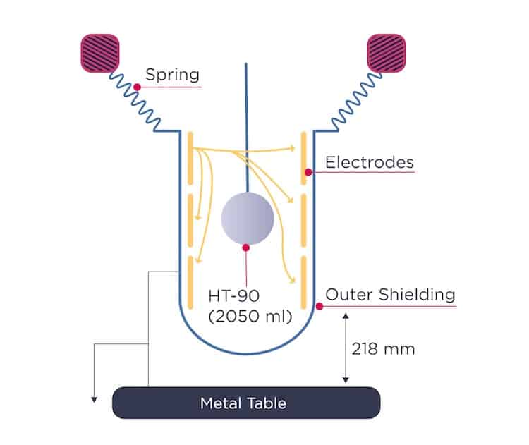
To better understand how this system would perform in space, the NIST team suspended a fluid-filled balloon inside the test tank, mimicking a liquid droplet in microgravity. They then input the resulting capacitance data into a software program to produce a series of 2D images, which they subsequently compiled to produce a 3D rendition of the balloon. The balloon’s measured diameter differed by less than 6% relative to its actual diameter.
Wet and dry spheres pack together in the same way

As well as gauging fuel, the researchers say the new ECVT sensor could help overcome other problems related to liquids in space. For example, Deshpande suggests that it might be used to continuously monitor fluid flow in the many pipes aboard the International Space Station and study how sloshing fluids can alter the trajectory of spacecraft and satellites.
The researchers, who report their experiments in the Journal of Spacecraft and Rockets, plan to further test and explore various image reconstruction techniques. They are also studying ways to incorporate their sensors into new generations of long-distance spacecraft.
“The flexible and inexpensive design and fabrication of these sensors may allow several of them to be used in a spacecraft or satellite fuel tank working independently to create a composite image of the total fuel volume,” Dagalakis tells Physics World. “These sensors could have different sizes and shapes for covering the surface of the tank, any internal piping, fuel feeding pipes and fuel concentration structures.”