Researchers have shown that certain metal-organic materials can act as permanent magnets at temperatures of up to 242 °C, while remaining magnetized in external magnetic fields as strong as 7500 oersteds – 25 times higher than other “molecular magnets” reported previously. Both values are comparable to various purely inorganic magnets available on the market today, suggesting a range of possible applications for magnets made from these lightweight and abundant materials.
Room-temperature magnets are usually made from pure metals, metal oxides or intermetallic compounds. Despite their ubiquity – they are crucial components of data processing and storage devices, electrical motors, renewable energy technologies and more – they suffer from several drawbacks. They are heavy, require a lot of energy to fabricate, and are made from raw materials that are sometimes difficult to source – especially for widely used rare-earth-based magnets like NdFeB and SmCo.
Promising alternatives
Magnets made from molecular building blocks such as organic ligands and paramagnetic metal ions are promising alternatives to purely inorganic magnets. As well as having similar magnetic behaviour to that of traditional magnets, their properties can be precisely tailored and optimized post-synthesis thanks to the flexibility of molecular and coordination chemistry, says team leader Rodolphe Clérac of the University of Bordeaux and CNRS in France. Indeed, researchers have already made magnetic structures that have no inorganic equivalent, including single-molecule magnets, single-chain magnets and 2D/3D networks with magnetically ordered phases.
Another advantage of molecule-based magnets is that they have very low densities (around 1 g/cm3) compared to their purely inorganic counterparts, which typically have densities over 5 g/cm3. This makes them attractive for emerging technologies such as magnetoelectronics, magnetic sensing and data storage, even though their maximum energy product – a measure of a magnet’s strength – is much lower. The snag is that most molecule-based magnets made to date can only operate at relatively low temperatures, which prevents them from being used more widely.
Increasing operating temperatures
To increase the operating temperatures of these magnets, researchers have tried linking radicals (that is, species containing at least one unpaired electron), to metal ions in 2D or 3D co-ordination networks. The strong magnetic coupling between the free electron spins of the radicals and the metal ion spins produce magnetically ordered phases that boast critical temperatures (that is, the temperature above which a material’s intrinsic magnetic moments cease to be regularly ordered) as high as 400 K in some cases. There is a price to pay, however, in that the room-temperature coercivity (a measure of the magnetic field needed to reduce the magnetization of a ferromagnetic material to zero) of these materials is low – on the order of hundreds of oersteds at best.
Clérac and colleagues have now used co-ordination chemistry – the combination of metals and ligands at the molecular level – to make a lightweight magnet with an ordering temperature of up to 242 °C and a 7500 oersted coercivity at room temperature. The magnet is made by the chemical reduction of pre-assembled co-ordination networks consisting of metal ions of chromium (an abundant metal) and inexpensive organic molecules known as pyrazines (pyz).
Enhanced magnetic interactions
Clérac and colleagues used lithium 1,2–dihydroacenaphthylenide in tetrahydrofuran to reduce two 2D co-ordination networks, CrCl2(pyz)2 and Cr(OSO2CH3)2(pyz)2. This strategy enhances magnetic interactions between the Cr ions and pyz molecules. Although structurally similar, these two materials have very different physical properties: while Cr(OSO2CH3)2(pyz)2 is antiferromagnetic below 10 K and an insulator, CrCl2(pyz)2 is ferrimagnetic below 55 K and an electrical conductor even at room temperature.
The researchers say that their molecule-based metal-organic magnets compare well with traditional inorganic magnets, while also boasting better magnetic properties and a higher critical temperature than previous molecule-based magnets. “The post-synthetic chemical reduction of co-ordination networks we have demonstrated is a general, simple and effective approach that could allow for the preparation of a new generation of high-temperature lightweight magnets with yet unrealized applications in emergent technologies,” Clérac says.
In the future, members of the team (which also includes researchers from the European Synchrotron Radiation Facility, ESRF), say they plan to develop a completely new family of molecule-based magnets with adjustable properties. “We also hope to find novel materials that could combine magnetic properties with high electrical conductivity at room temperature,” Clérac tells Physics World.
“Focused ultrasound is a rapidly expanding field – and if you look at research publications covering focused ultrasound in the brain, there’s an exponential rise in interest,” said Nir Lipsman, a neurosurgeon at Sunnybrook Health Sciences Centre. “A lot of this is due to the myriad ways in which focused ultrasound can interact with the brain.”
Lipsman was speaking at last week’s 7th International Symposium on Focused Ultrasound, where he described some recent advances in treating brain tumours with focused ultrasound (FUS). While ultrasound may be familiar to most for its use in medical imaging, FUS – which works by focusing multiple ultrasound beams onto targets inside the body – also serves as a therapeutic modality, exploiting a wide range of mechanisms to achieve different physiological effects.
In the brain, high-frequency FUS can be used to generate discrete targeted lesions, while low-frequency FUS, in combination with injected microbubbles, can facilitate drug delivery across the blood–brain barrier (BBB). Other potential applications include transient modulation of brain circuitry, targeted uncaging of nanodroplets for drug delivery and hyperthermia to enhance radiotherapy.
Tackling the BBB
Many of these applications could play a significant role in treating brain tumours, such as glioblastoma multiforme (GBM), the most common malignant brain cancer, which has limited treatment options. One big obstacle is it’s currently not possible to deliver targeted therapies across the BBB and into the brain. Various technologies have been investigated to breach the BBB, but all have cost limitations or associated risks.
FUS, on the other hand, provides a safe and precise way to bypass the BBB. Following injection of microbubbles, FUS is targeted through the skull onto a discrete part of the brain. Microbubbles exposed to ultrasound energy oscillate and physically pull apart cells in the BBB, allowing any circulating drugs to pass through, in concentrations that could ordinarily not be achieved.
“This is a mechanical process that opens up the BBB and does so reversibly,” said Lipsman. “This could be a window that allows us to gain access and deliver therapies.”
Lipsman was part of the team that performed the first human BBB opening in 2015, publishing the results of this first-in-human study last year. The team treated five patients with malignant brain tumours using MR-guided FUS alongside chemotherapy, demonstrating that the approach was safe and feasible.
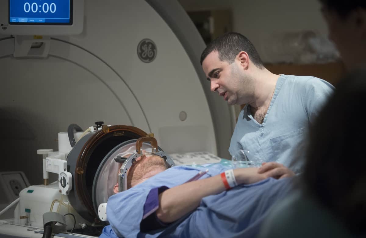
Since this phase I trial, the technology has evolved to allow treatment of much larger volumes, while upgraded software allows real-time visualization of BBB opening. The team is now running a phase II trial in patients with GBM, to define the safety profile of BBB opening in larger volumes. Lipsman noted that the procedure, which takes 2–3 hr, is performed with the patient awake and usually as a day procedure. “This is the first time that non-invasive day surgery of BBB opening to enhance the delivery of chemotherapy has been performed in large volumes,” he said.
Nir Lipsman with a participant in the trial of BBB opening in patients with GBM. (Courtesy: Kevin Van Paassen, Sunnybrook Health Sciences Centre)
The team is also investigating the use of FUS in patients with metastatic tumours to the brain. In breast cancer, for example, Herceptin can effectively treat breast metastases everywhere in the body, except the brain. The problem is that Herceptin is several orders of magnitude too large to get through the BBB and into the brain.
To address this, the team is now running an ongoing trial of FUS-enhanced Herceptin delivery in breast metastases to the brain. Results from the first two patients show that FUS can safely and reversibly open the BBB, and in highly sensitive regions of the brain. The next steps include radiolabelling the drugs to visualize their passage into the brain.
Liquid biopsy
FUS can also contribute to neuro-oncology in other ways, such as providing an improved way to determine whether a suspicious brain lesion is a tumour, and whether it requires surgical resection or could be treated using chemotherapy or radiotherapy. Currently, this diagnosis requires a brain biopsy, in itself a risky procedure.
Instead, the idea is to use FUS to open the BBB and enable a “liquid biopsy” based on a blood test. Opening the BBB results in increased detection of cell-free DNA – which can be tested to ascertain whether a lesion is cancerous. And the greater volume of BBB opened, the more cell-free DNA is detected in the blood.
“A means of opening up the BBB and potentially allowing us to peripherally detect what a lesion is by taking a blood test could lead to a more promising way of making a clinical diagnosis,” said Lipsman. “This will mitigate the need for open neurosurgery exclusively for the purpose of biopsy.”
Lipsman concluded that the many applications of FUS to oncology are arguably its most exciting. “We’re interested in developing this treatment, as are many centres around the world, for primary brain tumours and metastatic brain tumours. And we’re very interested in working with paediatric colleagues and developing applications for children,” he said. “The goal over the next five to 10 years is to run as many trials as we can. This is arguably one of the most exciting and most promising areas of clinical neurosciences.”
Researchers have found a way to grow layers of two-dimensional (2D) materials with predictable interlayer twists, dispensing with the need to stack and twist separately-grown layers by hand. The new technique uses curved growth surfaces and could provide a significant boost to the field of “twistronics” – a new approach to tuning the electronic properties of materials and engineering future devices.
In recent years, physicists and materials scientists have explored ways of using the weak (van der Waals) coupling between stacked, atomically-thick layers of material to manipulate the material’s properties. The most famous example is graphene, a 2D sheet of carbon atoms. Graphene does not normally have an electronic band gap, but it can be made to develop one when placed on top of hexagonal boron nitride (hBN), a 2D material with a similar lattice constant. If these stacked layers of graphene and hBN are twisted, however, the angle between the graphene and hBN lattices increases, reducing the van der Waals coupling and causing the band gap to disappear. In this fashion, graphene can be made to act like a metal or a semiconductor simply by varying the angle between layers. What is more, placing two layers of graphene together and rotating them at a “magic” angle of 1.1° relative to each other transforms metallic graphene into a superconductor.
This emerging science of “twistronics” thus offers a way of controlling a material’s electronic properties that does not require changing its chemical make-up, as conventional techniques (such as doping) do. But there is a problem: creating these stacks of materials usually requires researchers to exfoliate or synthesize layers of 2D materials separately before stacking and twisting them – a painstaking manual process.
Curved surfaces
A team led by Song Jin of the University of Wisconsin–Madison in the US has now overcome this challenge by exploiting non-Euclidean (curved) surfaces and a type of crystal imperfection called a screw dislocation to grow twisted 2D crystals. In 2D materials, these screw dislocations cause a spiral structure to form in which all the layers throughout the stack are connected and the orientation of every layer is aligned – sort of like a ramp in a multi-storey car park, Jin explains.
In their experiments, the Wisconsin researchers placed nanoparticles of silicon oxide under the centres of their spirals of 2D materials. This nanoparticle disrupts the previously flat surface, creating a curved foundation for their 2D crystal (made, in this case, from the transition metal dichalcogenides tungsten disulphide or tungsten diselenide) to grow on.
In this situation, instead of an aligned spiral in which the edge of each layer lies parallel to the previous layer, the researchers found that the 2D crystal forms a multilayer spiral that continually twists in a predictable way from one layer to the next. The angle of the interlayer twist stems from a mismatch between the flat 2D crystals and the curved surfaces they grow on, they explain, and two different types of spiral are possible. When a spiral structure grows directly over the nanoparticle, it creates a pattern that lead author Yuzhou Zhao dubs a “fastened spiral”. A structure grown over an off-centre nanoparticle, in contrast, is termed an “unfastened spiral”.
Models and measurements
To explain this behaviour, Zhao developed a mathematical model that predicts the twist angles of spirals based on the geometry of the curved surfaces. These modelled shapes generally agree with the structures he grew in the laboratory. In addition, electron microscopy measurements by Chengyu Zhang and Paul Voyles, also at Wisconsin, show that lattices of atoms on neighbouring twisted layers form an overlapping interference (moiré) pattern – as expected.
While the researchers used tungsten disulphide and tungsten diselenide to show how twisted material could be grown, they note that the concept of twisting spirals could be extended to other 2D materials. “We can now follow a rational model rooted in mathematics to create a stack of 2D layers with a controllable twist angle between every layer,” Zhao says. “Being able to directly synthesize twisting 2D materials in this way will allows us to study novel quantum physics in these materials.”
Full details of the research are reported in Science.
Vacuum technology is a ubiquitous presence in all manner of fundamental and applied physics research endeavours – from synchrotron light sources to semiconductor fabrication, from electron microscopy to quantum computing, and plenty more besides. Yet as any vacuum end-user knows all too well, cutting-edge research projects rarely stick to the script. As such, the process of designing, developing and manufacturing a turnkey vacuum chamber to support a diverse set of scientific applications is tricky at best and, when extrapolated over an extended timeframe, vanishingly hard to get right – not least when it comes to matching the chamber’s technical specifications versus research priorities that are, by definition, always fluid and always evolving.
Now, however, the Czech vacuum equipment manufacturer STREICHER Pilsen appears to have come up with an elegant and potentially game-changing concept that has the potential to both simplify and future-proof the design of scientific vacuum systems. In short: STREICHER Pilsen’s S-Cube modular vacuum chamber system offers researchers a controlled vacuum space where modification is the norm rather than the exception – an “evolve-as-you-grow” technology model that offers built-in flexibility, scalability and, as a result, many more design degrees of freedom versus conventional vacuum equipment. There’s an environmental upside as well, with the modular S-Cube approach enabling vacuum users to extend the lifetime of their vacuum chambers (rather than making cyclical investments in new hardware as research priorities change).
“Our S-Cube modular vacuum concept enables modification of the existing vacuum chamber by replacing only some of the walls or by adding another extension module,” explains Jiří Lopata, CEO of STREICHER Pilsen. “There is no need to manufacture a new chamber as the scientists’ research requirements change – a feature that ultimately translates into significantly lower capital outlay over time. Put simply: if you can adapt your existing vacuum system, you don’t need to invest in a new one.”
The new rules of vacuum
Near term, the priority for Lopata and colleagues is to raise awareness of the S-Cube product concept within STREICHER Pilsen’s established customer base – far from straightforward in the grips of a global pandemic. For context, the company has been manufacturing vacuum equipment and components for more than 25 years, serving OEMs and technology start-ups across a range of industries – chemical and pharmaceutical, semiconductor, food processing, heat treatment and steel manufacturing. Big science is another core market segment, with activities to date spanning high-profile projects for the Extreme Light Infrastructure (ELI) beamlines in central Europe; the Joint Institute for Nuclear Research (Dubna, Russia); and the Fusion for Energy project (which coordinates the European Union’s contribution to the ITER experimental fusion reactor in France).
According to Lopata, this diverse customer base – spanning industry and R&D – provides the foundation for STREICHER Pilsen’s core competency. “Our design and engineering teams have first-hand experience and deep domain knowledge about the production of custom vacuum equipment,” he explains. “S-Cube is a logical progression of that collective know-how. For us, it’s all about supporting the complex applications and ever-changing vacuum requirements of our customers, whether they’re in a research or an industry setting.”
Make it easy S-Cube users are able to design their own complex vacuum system by connecting a mix of basic building blocks comprising cubic, hexagonal and cuboid chamber modules. (Courtesy: STREICHER Pilsen)
For scientific end-users of vacuum systems, what’s particularly attractive about the S-Cube concept is its combination of simplicity, modularity and ease of customization – features that would be otherwise unthinkable with a conventional welded vacuum chamber. In effect, S-Cube users are able to design their own complex vacuum system by connecting – via standardized interfaces – a mix of basic building blocks comprising cubic, hexagonal and cuboid vacuum chamber modules (all available in a range of custom sizes, with wall lengths from 450 mm up to 2 m).
Yet while flexibility and customer choice are a given, there’s also a broader emphasis on system-level S-Cube solutions (see “Two heads are better than one”, below). “We always support our customers –not only with the design and production of the vacuum chamber, but with the entire vacuum system,” says Emil Černy, head of engineering at STREICHER Pilsen. “That means expert guidance regarding the optimum choice of vacuum pumps, valves, electrical feedthroughs and vacuum gauges, as well as easy-to-use systems for vacuum process control and data visualization.”
Customers also have a range of more granular options in terms of S-Cube functionality – for example, direct integration of an optical table on independent supports; specification of aluminium chamber walls within a stainless-steel system frame; as well as polished or sand-blasted internal surfaces. For now, all S-Cube chambers are compatible with low, medium and high-vacuum applications, though a planned option for metal sealing will ensure future support for ultrahigh-vacuum (UHV) systems.
Your vacuum, your way
When it comes to market-facing activity, it’s clear that S-Cube innovation also extends to the online presentation of the product offering. A case in point is the Configurator, a dedicated website that allows customers to design and optimize their own S-Cube vacuum chamber via an intuitive and easy-to-use interface. “Think collaborative product design,” says Černy. “The Configurator is our shop window – a great way for new customers to get to know the basic features of the S-Cube system.”
With the help of the online tools, for example, the user is able to equip removable chamber walls with a range of built-in accessories (hinges, flanges, locks and viewports), integrate an optical table, as well as define key pressure and temperature cycles. What’s more, all system variants are displayed immediately in a preview that can be exported to PDF for proofing and discussion with the STREICHER Pilsen design team.
“Ultimately, our goal is to make the interface with S-Cube technology as easy to use and as accessible as possible,” concludes Černy. “The Configurator puts the design capability in the hands of the customer, while our in-house technical team provides the specialist support to move them rapidly from a v1.0 specification to a finalized S-Cube chamber configuration.”
To fast-track the commercial roll-out of the S-Cube product portfolio, STREICHER Pilsen has teamed up with fellow vacuum manufacturer Edwards in what, the vendors hope, will be a win-win for vacuum customers in research and industry.
The formal collaboration kicked off earlier this year and sees STREICHER Pilsen offering a range of Edwards’ technologies – pumps, sensors, leak detectors and control systems – to end-users interested in purchasing not just a vacuum chamber, but a turnkey S-Cube vacuum system. This approach to the market will open up wider commercial opportunities for STREICHER Pilsen, while Edwards stands to gain new sales channels for its diverse product portfolio as well as its after-sales support and field-service teams.
“Our two companies have complementary rather than competing technology portfolios,” explains Radim Hlavaty, Edwards’ regional account manager (Czech Republic and Slovakia). “It’s also a logical collaboration in terms of proximity, given that Edwards has a large manufacturing facility in the Czech Republic.”
Notwithstanding the commercial drivers, there are other significant upsides to consider, notes Emil Černy, head of engineering at STREICHER Pilsen. “We can see real synergies for our respective design teams and application engineers,” he explains. “On our side, we’re benefiting directly from Edwards’ specialist capabilities in areas like vacuum simulation and system-level optimization, as well as gaining insights from their product development roadmaps for next-generation vacuum pumps.”
Once upon a time, air travel was risky, costly and highly polluting. But these days modern airliners are the safest way to travel long distances, as well as being cheaper, quieter and more fuel-efficient than their predecessors. If you need to cross the US, a seat on an Airbus will get you there on less than half the fuel of an average American car – and save you three days.
Unfortunately, this efficiency is a double-edged sword, encouraging more and more people to fly or send cargo by plane. Aviation’s contribution to the world’s CO2 emissions has risen from zero to 2% within the last century despite the fact that the litres of fuel burned per passenger-kilometre has plummeted – from 10.3 l/100 passenger-km for the De Havilland Comet 4 in 1958, when commercial flight with jet engine aircraft was new, to 2.42 l/100 passenger-km with today’s Airbus A330neo-900. Furthermore, with around 107,000 commercial flights taking place every day prior to the COVID-19 pandemic, noise pollution from airports is a huge concern.
Aviation’s contribution to the world’s CO2 emissions has risen from zero to 2% within the last century despite the fact that the fuel burned per passenger-kilometre has plummeted
Green solutions
So, what can be done to make aviation greener?Well let’s consider Boeing’s 787 Dreamliner – a modern airliner that looks much like its noisier, less-efficient ancestor, the 707. Each has a cylindrical fuselage with a square-root-of-x nose profile, wings swept back about 35°, and jet engines sticking forward from under the wings. This shape is set by the laws of mechanics and by compressible fluid flow.
Look closer, however, and differences emerge. The Dreamliner’s engines are fatter in front, so they have a high “bypass ratio” – they put less kinetic energy into the airstream for the same amount of thrust. The engine exhaust nozzles are scalloped with a chevron shape, which creates vortices in the exhaust fumes. When high-speed exhaust mixes with the slower-moving air, the vortices make less noise than the chaotic mixing of earlier engines.
More subtly, the leading edge of the 707’s aluminium wing is straight but the Dreamliner’s is curved, which reduces fuel-wasting drag. Although the shape is too complex to be affordably built with aluminium, it is made possible thanks to a composite material – carbon-fibre-reinforced plastic (CFRP). Besides allowing aircraft components such as the wings, tail and fuselage to have a wide variety of shapes, CFRP is stiffer and has a higher strength-to-weight ratio than aluminium or steel. These factors make the aeroplane lighter, so less fuel is needed to get it off the ground and keep it airborne.
One challenge of CFRP is in the factory, where it starts as a flexible fabric or tape infused with uncured epoxy resin. This is laid on moulds by hand or by automated tape-laying machines. To make it rigid, it then has to be “cured” or baked in an autoclave at temperatures of up to 180 °C, depending on the blend of CFRP. The problem is that ensuring that every region of the part stays at exactly the right temperature is tricky, calling for careful process control and sometimes for instruments embedded within the fabric. To verify that every ply of material (there can be as many as 100 layers) lies smoothly on the one below it with no wrinkles, voids or delaminations, aircraft manufacturers use inspection methods, such as machine-vision, for automatic checks while the tape is being applied, and X-ray and ultrasound to verify each part before it’s built into a larger structure.
When lightning strikes
A big issue for CFRP is that it has a very high resistance, which is a problem when a typical commercial airliner is struck by lightning at least once a year. A bolt can carry as much as 200 kA of electrical current, which enters at one location, such as a wingtip, and exits at another, like the tail. Aeroplanes that have skin and sub-structure of mostly aluminium easily handle the current and the heat it produces at the point of attachment: engineers only need to include good conductive paths between components, skins thick enough to prevent melt-through, and internal sealant over gaps or joints to prevent arcs and sparks.
Part of the problem is that CFRP conducts electricity anisotropically. Current flows fairly easily along the fibres, which are 2000 times less conductive than copper but 30 times more conductive than silicon. However, current flows poorly between the fibres or between ply layers. Electrical potential from a lightning strike may therefore arc through the air to get around non-conductive zones, or the current may heat fibres and create a spark of vaporized material – either of which could cause a fire in a fuel tank.
Governments and manufacturers have therefore developed ways to avoid arcs and sparks. Metal foils, for example, are used on the outside of a plane to guide lightning current and protect composite skins. Other techniques include using dielectric material to isolate current and direct it away from sensitive components, and minimizing resistance in fastener installations. There are also laboratory experiments and software that can simulate lightning current, allowing us to get a better theoretical and experimental understanding of lightning attachment, arc conditions and ignition processes. Engineers can then use this knowledge to design aircraft with large margins of safety above the strongest lightning strike. These efforts have paid off. Aircraft built with CFRP wings and fuselages are routinely struck by lightning, just like their aluminium siblings, but none has had an ignition. The challenge now is to reduce the weight of these solutions so fuel economy gets even better.
While heating and arcing are direct effects of a lightning strike, it can also cause indirect effects by inducing voltage, current or force in components where the lightning current doesn’t reach. For example, a fast-changing lightning current can induce a voltage that flips a bit in nearby electronics, or it can induce eddy-current forces so strong they bend or break some components. Designers use modelling and testing to verify that indirect effects cause no problems, or that counter-measures such as shunt diodes or shielded cables keep a current spike from reaching a sensitive component.
Sweeping wings
On an aeroplane, the wings’ job is to lift the craft against gravity. It does this by deflecting air downward, which imparts downward momentum to the air and an equal upward momentum to the wings. The structure inside the wing transfers the force to the fuselage (the body of the plane) thereby allowing the aircraft to fly.
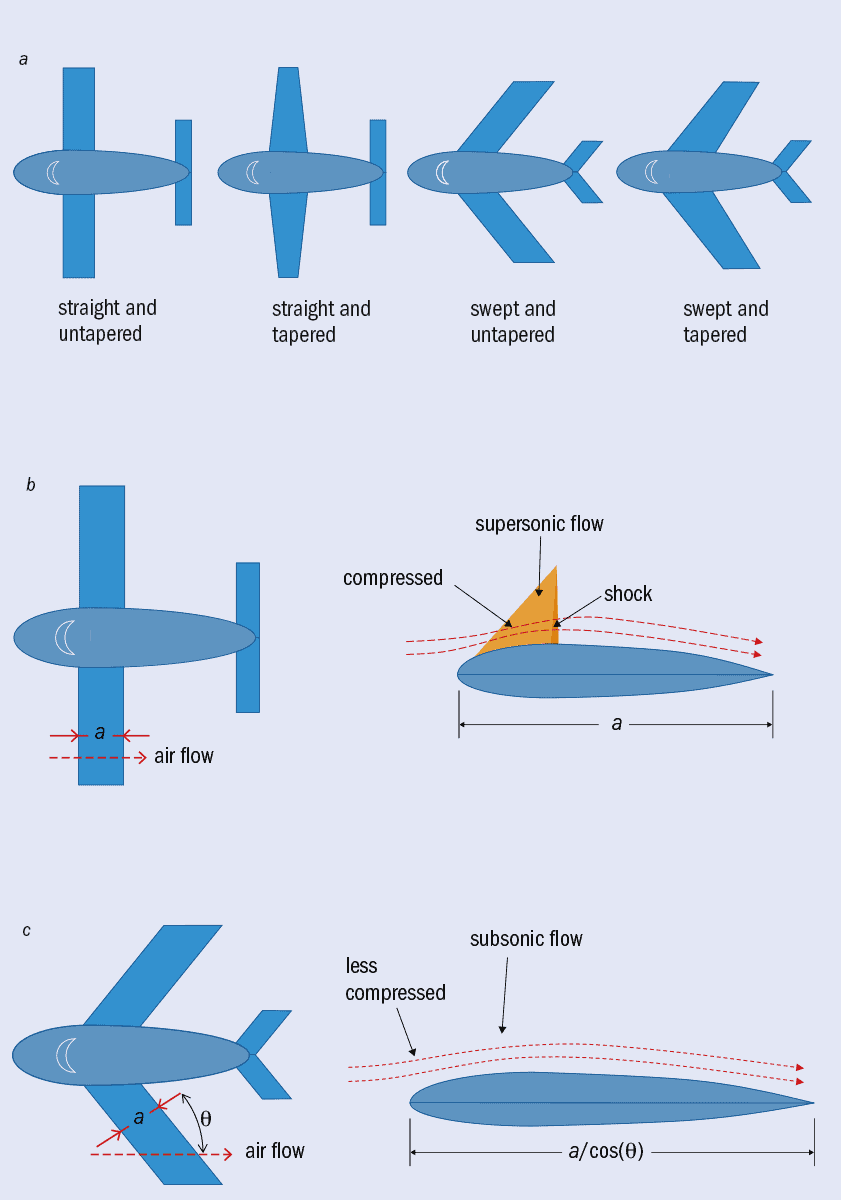
(a) Early planes featured straight, thick wings – indeed, some modern small aircraft still do. While these are structurally efficient, requiring little mass to safely transfer lifting force to the body, a tapered wing is even better. The structure is lighter than for straight wings because most lift is produced by the thick region near the fuselage, meaning it only has to transfer that lift a short distance.
A plane can also be made more stable if there is slight sweep back on the leading edge. For a plane flying straight, the wings have equal cross-section to the airstream. When the craft twists to the right, perhaps from a gust of turbulence, a swept left-wing presents a larger cross-section to the wind than the right wing. This helps the aeroplane quickly straighten out after small disturbances.
For planes with jet engines, the wings are swept back even further than for their slower, non-jet-engine counterparts – in some cases they can even be angled at more than 40°.
Jet engines allow planes to fly near the speed of sound, at transonic speeds. Air flowing over curved or thick parts of the plane must move even faster than the speed the plane is travelling, often meaning it reaches supersonic speeds (faster than the speed of sound). So when that supersonic airflow moving over those thicker parts of the wing collides with slower moving air, it creates shockwaves. A shock irreversibly transforms the air’s kinetic energy into heat and that loss of energy creates lots of drag.
The engineers who built early jets solved the problem by sweeping the wings. (b) With a straight wing’s profile, in the thick region, airflow is supersonic. (c) With a swept wing, the air follows a gentler path. Its arrival at the thick part of the wing is delayed by a factor of 1/cos(θ), where θ is the sweep angle. Air farther from the wing has more time to shift out of the way, so air near the wing has a wider “channel”. It needn’t go supersonic to get around the wing.
The next generation
Though the shape of airliners has changed little over the last 60 years, the cantilevered swept-wing shape may, over the next decade or two, finally give way to a new design thanks to NASA and companies like Boeing, which are developing the “transonic truss-braced wing” that will exhibit little or no sweep.
Conventional truss-braced wings with no sweeping V-shape are an old idea and the design is still popular for small aeroplanes. In fact, the world’s best-selling aircraft, the four-seat Cessna 172, has a straight truss-braced wing. Until now, however, no jet airliner has used an unswept wing, truss-braced or not, because it produces too much drag at transonic speeds, those that are near or at the speed of sound (see box above). Airliners usually travel at Mach 0.8–0.85, where the Mach number is the fraction of the speed of sound in the local atmospheric condition (343 m/s in dry air at 20 °C) – typically the actual speed is 246–271 m/s (885–974 km/h) depending on air temperature.
New, thin airfoils made possible by CFRP, plus structural bracing by thin CFRP trusses, finally allow for wings with little or no sweep that can travel at these speeds without producing too much drag. The advantages of an unswept wing include the fact that it is structurally more efficient than a swept-back wing. To have a given wingspan, a swept wing must be longer than an unswept one. The wing’s lift then acts with a longer moment arm, which increases the bending moment on the wing’s structure. To resist this, the structure of the swept wing must be stronger, and therefore heavier, than an unswept one.
The external truss also reduces stress on the wing’s internal structure so the wing can be thinner top-to-bottom, giving it a small frontal cross-section and thereby reducing drag. To cut drag more, the wing is narrower front-to-back than a traditional wing, which lets laminar flow cover a larger fraction of the wing surface. The wing is also longer relative to its front-to-back width, or “chord”, and this higher aspect ratio reduces the energy lost when high-pressure air from below the wing flows around the wingtip to the low-pressure region above the wing. An upward-folding tip allows this long-winged aircraft to fit into the small gates of regional airports.
Electric aeroplanes
Another way to make planes greener is to develop hybrid propulsion, rather like we now have hybrid cars. The idea is that jet turbines would boost power for take-off while batteries or fuel cells would provide steady power for cruise. Of course, it would be even better if aeroplanes could fly purely on renewable energy (such as solar or hydro) or nuclear power, which emit no carbon.
Alas, an all-electric airliner to replace today’s planes is not on the cards. Batteries have a specific energy (measured in joules per kilogram) that is orders of magnitude lower than the specific energy of hydrocarbon fuel. This figure will improve, but not enough. That’s because when weight matters, as it does in aeroplanes, batteries will always suffer from the fact that they have to carry their own oxidizer, whereas fuel-burning engines use oxygen from air. Therefore, a battery-powered aeroplane or helicopter can only work over tens or perhaps hundreds of miles, not over the thousands of miles where an aeroplane’s speed makes it most useful.
A battery-powered aeroplane or helicopter can only work over tens or perhaps hundreds of miles, not over the thousands of miles where an aeroplane’s speed makes it most useful
There are a few prospects on the horizon for getting around the fundamental limits of batteries. One option is to use lasers or microwaves to transmit energy from the ground to aircraft in flight. The beam of photons creates voltage and current in dipole antenna elements or photovoltaic arrays on the aircraft, with diodes siphoning off the power to run motors or electronics. This has been done at a small scale. One of the best demonstrations was by the SHARP project in Canada back in 1987 using microwaves, but more recent efforts include Lockheed Martin and LaserMotive (now PowerLight) flying an unmanned aerial vehicle (UAV) using laser beams. However, the method faces regulatory and cost challenges before it can scale up to commercial flight.
As for solar-powered aircraft, they do already exist, but because the sunlight is so weak, these fragile aircraft fly slowly and with little payload. A third option is to recharge aircraft in flight, just as aerial tankers transfer fuel to military aircraft today. It’s plausible for long-range all-electric flight, but technical challenges remain.
From super to hypersonic airliners
Another development that we could see over the next two or three decades is hypersonic travel, which means craft flying at Mach 5 (6126 km/h) or faster. This kind of speed could get you from Los Angeles to Beijing in no more than two hours. Supersonic airliners – the Concorde and the Tupolev 144 – only flew at half that speed and gave off huge amounts of CO2. They were also horribly noisy at take-off and landing, and emitted sonic booms during cruise. Both are now out of operation.
Hypersonic airliners will do better. These new aircraft will likely use hydrogen – produced by electrolysis using non-fossil energy sources – or low-carbon fuel like methane. With such light molecules, the fuel and air can rapidly mix, which is vital because air moves through the engine so fast it spends only a few milliseconds in the combustion zone.
The future of flight Concept images of a future commercial airliner with straight truss-braced wings (left, courtesy: NASA/The Boeing Company) and a low-sonic-boom hypersonic aircraft (right, courtesy: Lockheed Martin).
Sonic boom is less of a problem now, too. NASA is already developing low-boom aircraft designs, which have a long, sharp nose that reduces the area over which air is compressed to form the leading shockwave. They also keep protuberances, like the engine intake, on top of the fuselage so shockwaves produced there go up, not downward to bother people.
What’s more, thanks to a quirk of the atmosphere, most acoustic energy from hypersonic planes will never reach Earth. If you imagine a sonic boom heading out diagonally down from an aircraft, the sound will meet steadily warmer air as it moves. Given that sound and shockwaves travel faster in warm air, the sonic boom will refract – its path will curve and become more horizontal as it moves lower. So apart from shockwaves that are heading almost straight down, the path eventually curves upward, avoiding the ground altogether. And because hypersonic aircraft fly at 27,000 to 30,000 m – more than twice as high as today’s airliners, because higher altitudes mean thinner air and therefore less drag – nearly 100% of the sonic boom refracts away from the Earth.
Despite these benefits, several challenges of hypersonic flight must be overcome. One is the fact that air at the nose and leading edge of a hypersonic plane can get hotter than 1300 K because the air’s kinetic energy becomes heat energy when it runs into the perpendicular surface and stops. At those temperatures, CFRP, which has revolutionized today’s airliners, simply doesn’t hold its strength. Fortunately, titanium alloys and other advanced, lightweight materials – some with honeycomb structures to reduce heat transport – are being developed to solve this problem.
Another issue is ionizing radiation. When a galactic cosmic-ray particle strikes a nucleus in the upper atmosphere, the nucleus shatters into a spray of secondary particles. The trails of these secondaries create conductive paths in semiconductor electronics. Today’s planes fly at altitudes of 9000–13,000 m, where the secondaries are spread out, so any one electronic device sees only a small effect. But for a hypersonic plane flying at 30,000 m, the secondaries will be tightly clumped still, creating a much stronger radiation environment. It wouldn’t be a problem for passengers; a flight will be so short that the total dose would be lower than in today’s flights. But electronics will have trouble. A single chip may be hit by many secondaries at the same time, and such a sudden rise in conductivity can cause errors in a semiconductor chip, or even damage it permanently. Costly solutions do exist for spacecraft, such as physical shielding or electronics made of expensive materials with large band gaps. The challenge is to devise solutions for aircraft that are affordable and lightweight.
Urban aviation
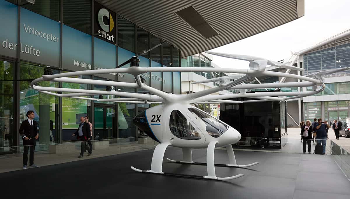
Sky taxi Aircraft like this helicopter developed by Volocopter could be roaming our city skies taxiing people and cargo. (Courtesy: CC BY-SA 4.0 Matti Blume)
With towns and cities suffering from rising congestion on the roads, there is a growing demand for an aircraft that can land vertically in a small space, load one or two people or a van-sized cargo, and fly above the clogged highways to another spot in the same city. That’s where battery-powered helicopters could be the answer. With four or more rotors, these electric “rotorcraft” will soon be carrying cargo, and perhaps passengers, in cities. Their short range – a few dozen miles – is a perfect match for urban flight.
This new family of aircraft has many environmental benefits. Because they fly at about 320 km/h and use uncongested routes, each aircraft can make as many trips per day as, say, 10 cars or trucks. If that happens, it gets 10 vehicles off the roads, making our commute a little easier. Each aircraft would also mean that 10 cars or trucks wouldn’t need to be built, saving energy and materials. Of course, being electric-powered, the aircraft emit no CO2 in cities where electricity comes from non-fossil sources. It also helps keep engine noise tolerable.
Challenges remain, however. For a two-person taxi service, the aircraft would have to be recharged quickly. The 15-minute charging time of today’s batteries would need to be shortened, or ways would have to be found to quickly swap depleted batteries for charged ones. Batteries would go through up to 20 deep discharge cycles per day, so they would reach end-of-life in a few months as the electrochemical process involved in a rechargeable battery isn’t totally reversible. That’s because with each charge–discharge cycle, some atoms from the electrodes or the electrolyte go to the wrong place, eventually weakening the battery and making it potentially develop too much leakage current to hold charge for long. Discarding or refurbishing the batteries at the required rate will therefore be a challenge.
Helicopters are also noisy, as is any vehicle with many small rotors. There are ways to make them quieter, like ducts around the rotors, but these have costs and trade-offs.
Finally, the density of air traffic would be unprecedented; a thousand aircraft simultaneously flying in an area the size of Los Angeles or London will require a new, and probably automated, approach to air traffic control. Computers, not humans, would have to pilot these vehicles and co-ordinate with traffic control.
In essence, the commercial aviation sector is continuing to refine and develop traditional aircraft as it has throughout its 100-year-old history, constantly seeking to reduce costs and lower their impact on the environment. But there are now new directions for the industry too, in the form of super-efficient new airliners that will look quite different, electric-powered rotorcraft that revolutionize urban transport (see box above), and hypersonic aeroplanes that protect the world’s environment while shrinking the distance between its people. Within decades, air travel may look very different to now.
Probability maps of white matter hyperintensities for healthy controls (top row), patients with mild cognitive impairment (middle row) and patients with Alzheimer’s disease (bottom row). (Courtesy: Acad. Radiol. 10.1016/j.acra.2020.07.039)
Every year, there are 10 million new cases of dementia, according to the World Health Organization. Despite this, our understanding of this condition is limited and our ability to identify its signs in the brains of patients is crude. New research from NYU Langone Health may improve our ability to identify early signs of dementia and cognitive decline from a patient’s brain scans.
How to spot the difference
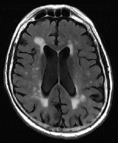
Diagnosing dementia is particularly challenging for doctors, with no test able to give a straightforward “yes or no” answer. What’s more, even the tools we do have are limited. An MRI scan allows us to see into the brain and observe bright spots, called white matter hyperintensities.
Brain MRI showing white spots near the centre that can be linked to dementia and cognitive decline. (Courtesy: Elsevier/Academic Radiology)
Having more of these spots, especially in the centre of the brain, is linked to dementia and other conditions that cause damage to the brain. Right now, though, identifying these spots and their extent is just a matter of having a “trained eye”, according to researchers behind a new study in the journalAcademic Radiology.
The team, led by Jingyun Chen from the department of neurology and Yulin Ge from the department of radiology, aimed to produce a more objective way to characterize these bright spots on brain scans. To achieve this, the researchers developed a new algorithm that is able to identify two different types of bright spots more consistently than alternative approaches.
This information could be used to distinguish between brain scans from healthy patients, patients with cognitive decline and patients diagnosed with Alzheimer’s disease more accurately than other methods. In fact, in tests on 72 MRI scans from 60 subjects, seven out of 10 of the algorithm’s predictions matched the patient’s clinical diagnosis.
Putting brain scans to the test
The method works by finding the precise position and volumes of all white matter lesions present in the scans. These are then analysed and classified based on the distance to both sides of the brain, to characterize which are the more concerning spots close to the centre of the brain and how large they are.
“Our new calculator for properly sizing white matter hyperintensities, which we call bilateral distancing, offers radiologists and other clinicians an additional standardized test for assessing these lesions in the brain, well before severe dementia or stroke damage,” says Ge.
Whilst the researchers are clear that their tool cannot be used alone to diagnose dementia, “amounts of white matter lesions above the normal range should serve as an early warning sign for patients and physicians,” according to Chen.
Having started with a limited series of scans, the team aims to analyse hundreds more to hone their method and has made the code freely available to other researchers and clinicians. As systematic methods for analysing these scans continue to improve, doctors will soon hopefully be able to use more than just their eyes to routinely track down key signs of brain disease.
A graphene-based memory resistor (memristor) that can exist in many different states has been designed and demonstrated by Thomas Schranghamer, Aaryan Oberoi and Saptarshi Das at Pennsylvania State University in the US.
Using simulations and experiments, the team showed how the device can be used to substantially improve the performance of artificial neural networks – systems that could someday rival and even replace conventional computers.
Despite decades of relentless growth, advances in the semiconductor technologies used in digital computing are showing clear signs of slowing down. To keep up with a growing demand for computing power, researchers are developing new technologies that mimic the operation of neurons the human brain – which perform both the storage and processing of information. This has the potential of being much more efficient than current computer architectures, which require both time and energy to shuttle data between separate storage and processing components.
Synaptic weight
In principle, this could be achieve using artificial neural networks (ANNs), which learn to do tasks by being given examples. ANNs are networks of artificial neurons that influence each other via synapses. The strength of the influence between neurons is called the synaptic weight, which can change during the learning process.
One way of adjusting synaptic weight is to use memristors, which are nascent electronic devices that exist in conductance/resistance states that depend on the amount of charge that has flowed through them. Ideally, memristors used in ANNs would have large numbers of conductance/resistance states, but current memristor designs tend to be binary – meaning they can only operate with two states.
Now Das and colleagues have created a graphene-based memristor that has 16 conductive states that can be reliably stored and read out. “What we have shown is that we can control a large number of memory states with precision using simple graphene field effect transistors,” Das says.
Arbitrary conductance values
The team also showed that unlike the fixed states in conventional memristors, those in graphene-based devices can be easily programmed to have arbitrary conductance values. This flexibility could make them even more valuable for creating ANNs. Finally, the team demonstrated a computational technique for assigning synaptic weight values in a smart way, enabling the levels of accuracy required by complex ANNs.
The trio hopes that their design will lead to new developments of space-efficient, high-speed, and low-power neural networks, which could be scaled up for commercial applications in the future. If achieved, these efforts could soon see the widespread use of graphene-based memristors, in emerging technologies ranging from self-driving cars to the Internet of things.
Officials at the US National Science Foundation have decided to decommission the Arecibo Observatory as a result of the cable failure.
A second cable has failed at the iconic Arecibo Observatory in Puerto Rico – and engineering teams have been brought in to assess the remaining cables, which are holding up the telescope’s metal platform suspended above the 305 m-wide reflecting radio dish. According to a statement from the University of Central Florida, two of the remaining main cables seem to have wire breaks, increasing the likelihood of the tower platform falling and destroying the telescope.
It is not an end that this telescope deserves
Laura Spitler
Since it opened in 1963, the Arecibo Observatory has been crucial for radio astronomy and is currently the world’s second-largest single-dish telescope. On 10 August, however, one of the six 8 cm-wide auxiliary steel cables that support the telescope’s platform failed and crashed down, tearing a 30m gash through the main reflector dish.
The six auxiliary cables had been added in the 1990s to help balance the increased weight when the reflecting system was upgraded.
According to Arecibo director Francisco Cordova, the cable appears to have failed due to a manufacturing process error, adding that Hurricane Maria in 2017 and recent earthquake tremors have accelerated the degradation.
Following the first failure, the remaining cables should have held the additional load, but for a still-unknown reason, that did not happen. Compounding the issue, on 6 November one of four main cables snapped, transferring the load onto the remaining cables and so making them more likely to fail. Indeed, there are concerns that further auxiliary cables from the same manufacturer may be faulty, with two replacement cables due to arrive in Puerto Rico in December.
Crisis time
The Arecibo Observatory is working with three engineering firms to assess the situation using drones and remote cameras. They will look at ways to reduce that load by temporarily repairing the August failure by either adding a new cable or relieving some of the load from the tower.
But these options will take several weeks and any temporary or permanent fix must be proposed to, approved by, and funded by the National Science Foundation – one of the organizations that manages the observatory together with the University of Central Florida, Universidad Ana G. Méndez and Yang Enterprises Inc.
“It’s a crisis,” says Michael Nolan of the University of Arizona and a former Arecibo director. “But I’m cautiously optimistic that they will find a way to take that tension off [the remaining cables].”
Laura Spitler from the Max Planck Institute for Radio Astronomy in Bonn, Germany, who has used the instrument to study transient radio sources, says losing the telescope would be a devastating blow to astronomy. “It would mean that one of the most important telescopes is gone,” she says. “It is not an end that this telescope deserves.”
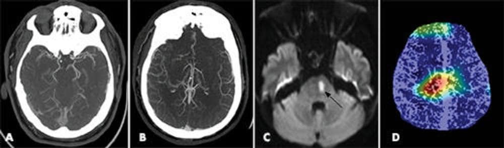
Examples of patients with large vessel occlusions correctly predicted by the deep-learning model. Top row: CT angiography slices; middle row: maximal intensity projection images; bottom row: heatmaps showing the most discriminative regions, which strongly correlate with occlusion location. (Courtesy: RSNA)
Strokes are life-threatening medical emergencies where urgent treatment is essential. They occur when part of the brain is cut off from its normal blood supply. The most common type of stroke (accounting for almost 85% of all cases) is an ischemic stroke, which is caused by a clot interrupting the supply of blood to the brain. Large vessel occlusion (LVO) strokes occur when such a blockage is found in one of the major arteries of the brain. As LVO strokes are more severe, they require immediate diagnosis and opening of the blocked artery as fast as possible.
In clinical practice, the most common method used to detect LVOs is an imaging modality called CT angiography. This method provides clinicians with a detailed, 3D image of the blood vessels in the patient’s brain. A newer CT technique, multiphase CT angiography, provides more information than its single-phase counterpart through the acquisition of cerebral angiograms in three distinct phases: peak arterial (phase 1), peak venous (phase 2) and late venous (phase 3). The main advantage of this method comes from its potential to detect any lag in filling of vessels, thus allowing the clinicians to perform a time-resolved assessment.
A group of researchers led by Ryan McTaggart from Brown University has developed a tool with the potential to quickly identify and prioritize LVO patients in an emergency setting. To achieve this, they built and trained a convolutional neural network capable of classifying the presence of LVOs on CT angiographies. This is the first study that uses deep learning to identify LVOs in both anterior and posterior arteries using multiphase CT angiography images. Their results are summarized in Radiology.
A deep-learning model that can classify LVOs…
To train, validate and test their model, the researchers used a dataset of 540 subjects with multiphase CT angiography exams. Of these, 270 patients had confirmed presence of an LVO, while the other 270 were LVO-negative. Each CT scan underwent a series of pre-processing steps.
First, the researchers standardized their scans through isotropic resampling (voxel resolution of 1 mm3), image resizing (500 x 500 pixels) and intensity normalizing (between 0 and 1). Then, they employed a vessel segmentation algorithm to increase the images’ signal-to-noise ratio. Finally, to further enhance the blood vessels, they selected 40 most-cranial axial slices from each subject and produced a single 2D image through a technique called maximal intensity projection.
To evaluate the diagnostic performance of the proposed deep-learning model, the group decided to experiment with seven training strategies. In each strategy, the team used a different subset of the multiphase CT angiography data: each phase alone, or various combinations (phases 1 and 2, phases 2 and 3, phases 1 and 3, and all three phases together).
… achieves high diagnostic performance
The group used a dataset of 62 patients (31 LVO-positive and 31 LVO-negative) to test their seven strategies. The model performed best when using all three phases as the input, where it achieved a sensitivity of 100% (31 out of 31) and a specificity of 77% (24 out of 31). Moreover, combining the peak arterial (phase 1) and late venous (phase 3), or the peak venous (phase 2) and late venous (phase 3), resulted in significantly better models than using just single-phase CT angiography.
Example of a false-positive prediction that showed no evidence of infarct on the CT angiography data (A: arterial phase; B: venous phase), together with a diffusion-weighted MRI acquisition (C) that found a small ischemic infarct. D: the heatmap shows localization of the blockage in the patient’s brain. (Courtesy: RSNA)
The model gave good predictions across patient demographics, multiple institutions and scanners. Also, it detected both anterior and posterior circulation occlusions. “[Our model] could function as a tool to prioritize the review of patients with potential LVO by radiologists and clinicians in the emergency setting,” the researchers conclude. For future work, the group aims to evaluate the model’s clinical utility by testing it in a real-time emergency setting.
The Japanese physicist Masatoshi Koshiba, who shared 2002 Nobel prize for the detection of cosmic neutrinos, died on 12 November aged 94. One of the founders of neutrino astronomy, Koshiba’s most famous work involved detecting neutrinos from a distant supernova explosion using a vast detector based in a mine in central Japan. He shared half the 2002 Nobel prize with Raymond Davis Jr “for pioneering contributions to astrophysics, in particular for the detection of cosmic neutrinos”. The other half went to Riccardo Giacconi for his work on the discovery of cosmic X-ray sources.
Koshiba was born on 19 September 1926 in Toyohashi, Japan and graduated from the University of Tokyo in 1951. He then moved to the US to complete a PhD at the University of Rochester, graduating in 1955. After three years at the University of Chicago he moved back to Tokyo, where he remained for the rest of his career.
In the 1980s, Koshiba was instrumental in the construction of a neutrino detector located 1000 metres underground in a lead and zinc mine in Japan. Called Kamiokande, it was an enormous water tank surrounded by photomultiplier tubes to detect the flashes of light produced when neutrinos interacted with atomic nuclei in water molecules.
Koshiba created a legacy that will continue to drive the field forward making scientific advances for many years
Dave Wark
Although vast numbers of neutrinos are produced by the Sun, they are difficult to detect because they interact very weakly with matter. In 1967 Davis, who was then at the Brookhaven National Laboratory, built the first experiment to detect solar neutrinos. Consisting of 600 tonnes of dry-cleaning fluid in the Homestake gold mine in South Dakota, it detected less than half the flux of neutrinos predicted by widely accepted models of the Sun.
The results – known as the “solar-neutrino problem” – could be explained only if these models were wrong or if the neutrino had mass. For 20 years Davis’s detector was the world’s only solar neutrino detector. But 20 years later Koshiba and colleagues began taking data with their Kamiokande detector and in 1987 confirmed the lower-than-expected neutrino flux that was reported by Davis by detecting neutrinos from a distant supernova explosion. For this work, Davis and Koshiba were awarded the 2002 Nobel Prize for Physics.
Creating a legacy
In 1998, Kamiokande’s successor – SuperKamiokande – found convincing evidence for neutrino mass in the form of oscillations between tau and muon neutrinos, which required new physics beyond the Standard Model of particle physics. This result led to Takaaki Kajita, a former student of Koshiba, sharing the 2015 Nobel Prize for Physics with the Canadian physicist Arthur McDonald for the discovery of neutrino oscillation.
In comments to the Mainichi newspaper, Kajita said that Koshiba had taught him everything about physics. “I was very lucky to be able to meet Koshiba, and it was very important for me in becoming a scientist,” he said.
Neutrino physicist Dave Wark from Oxford University in the UK, who has been involved with the Super Kamiokande experiment for the past two decades, says that it was Koshiba’s “force of will” that got Kamiokande approved in Japan and the Nobel laureate’s initiative that led to the creation of the huge photomultiplier tubes that have “been so important in the advance” of neutrino physics. “The sequence of Kamiokande leading to Super Kamiokande and now to Hyper Kamiokande has so far earned two Nobel Prizes, vindicating his original vision,” Wark told Physics World.
Wark adds that Koshiba was “a great guy to be around, filled with insight and energy and humour” and that Koshiba has “created a legacy that will continue to drive the field forward making scientific advances for many years”.