Femtosecond photonics: precision meets robustness

Femtosecond fibre lasers are all about versatility. With ultrashort pulse durations of just tens of femtoseconds (in the 10—15 s regime), and with different models covering visible through mid-infrared wavelengths, these compact, robust and reliable rare-earth-doped fibre sources have carved out diverse applications across science and industry – from additive manufacturing to molecular “fingerprinting”, from nanoscale spectroscopy to timing distribution in particle accelerators.

Now German precision photonics specialist Menlo Systems, a leading developer and supplier of femtosecond fibre lasers, is taking that versatility to another level. The manufacturer traces its origins two decades ago to the development and subsequent commercialization of optical frequency-comb technology (an invention for which Menlo’s co-founder, Theodor Hänsch, was a joint recipient of the 2005 Nobel Prize for Physics). Today, those optical frequency combs are routinely employed in fields as diverse as time and frequency metrology, spectroscopy, optical communications and fundamental physics.

In the course of its evolution, Menlo Systems has maintained something of a balancing act. On the one hand, the company has built its commercial success around high-precision and customized optical solutions for scientific customers all over the world – whether that’s smaller research groups or large-scale facilities like CERN in Geneva and the SACLA free-electron laser in Japan. At the same time, the manufacturer has forged long-term relationships with OEM industry customers, understanding their problems and gathering technical requirements to inform product development across the Menlo technology portfolio.

Those industry customers, for their part, are seeking femtosecond fibre laser systems that deliver against their core metrics – reliability, robustness, footprint, cost:performance ratio and the like – while scientific customers put the focus on parameters like superior pulse-to-pulse stability, lowest relative-intensity noise and excellent beam quality. For the latter, the dialogue with Menlo’s product development team is crucial and necessitates an extended commitment from vendor and research customer, often running over many months or even years (see “Overcoming time delays with photonics”, below).

“The process involves mutual learning – usually in a research setting – and iteration of technology solutions in close collaboration with the scientific customer,” explains Christian Mauser, product manager for femtosecond fibre lasers at Menlo Systems.

A novel concept for better lasers

To support the diverse functional requirements for its femtosecond fibre lasers – whether in fundamental science, OEM industry applications or even space-based instrumentation – Menlo Systems developed its own mode-locking technology, based on an all polarization-maintaining-fibre design with no lifetime-limiting components. The key building block is a fibre oscillator that exploits Menlo’s patented “Figure 9” mode-locking technology – a robust optical set-up that combines simple, compact and reliable operation to yield several advantages versus other mode-locking approaches.

Our all-fibre mode-locking technology delivers outstanding performance, even in harsh environments.

Christian Mauser, Menlo Systems

“Our all-fibre mode-locking technology delivers outstanding performance, even in harsh environments,” explains Mauser. As a result, Menlo’s fibre lasers are suitable for portable operation in industrial manufacturing applications, while the excellent laser parameters give research users the reliability they need in a variety of settings – from imaging studies in neuroscience to next-generation materials microprocessing.

Equally important is the versatility of Menlo’s femtosecond fibre lasers. For starters, the timing jitter of the lasers’ output pulses is extremely low (in the attosecond and low femtosecond range), a feature that allows for creation of a timing master signal for precise coordination within a complex interplay of processes and events – for example, experiments at accelerator facilities or geodetic observatories. Further, Menlo’s proprietary intracavity actuators enable a particularly low phase-noise level over a wide range of laser repetition rates. “This is critical in applications with stabilized lasers, such as the interrogation of optical transitions in atomic clocks,” says Mauser.

Notably, all of these capabilities can be transferred to other wavelength regions (from 500 nm to 15 microns) via nonlinear frequency-conversion processes. Given Menlo’s vertically integrated structure, Mauser and his colleagues are also able to provide synchronization of the lasers to an external reference in a master–slave configuration, with fixed or tunable repetition rate. The master might be another laser, a hydrogen maser, or some type of RF signal.

Mauser adds: “It’s worth noting that other laser companies use our femtosecond fibre seed lasers and synchronization electronics to build their own laser systems. For the ‘drift-free’ distribution of timing signals, we offer all the necessary technologies – including stabilized fibre links, cross-correlators or balanced photodetectors – to ensure a timing precision of a few fs over distances reaching nearly 1 km.”

Overcoming timing delays with photonics

Anlage_Wettzell_mod_40pc-lores

Scientists, it seems, are able to bend time to their will in at least some respects using the Timing Distribution and Synchronization System (TDS) from Menlo Systems. Built around a femtosecond optical pulse source – an optical femtosecond oscillator using an erbium-doped fibre in Menlo’s “Figure 9” design – the TDS distributes a master RF or optical reference “clock” throughout a large-scale research facility with minimal added phase noise and drift (<10 fs rms).

“Timing distribution gets really challenging really quickly if you want high accuracy,” explains Pablo Dominguez, TDS product manager at Menlo. “My role is to enable that synchronization and make it work 24/7 without operator intervention. Instabilities over days and weeks shall be of the order of a few femtoseconds, whether that’s in a particle accelerator or free-electron laser facility, a radio-telescope array or a geodetic observatory.”

Menlo’s TDS system was originally developed for pump-probe experiments in linear accelerators, though other applications are now emerging. One of Menlo’s flagship TDS customers is the Geodetic Observatory Wettzell, a geosciences research centre in Bavaria that’s engaged in fundamental studies of continental drift, sea-level changes and Earth’s gravitational field, as well as a range of reference measurements to support satellite navigation, geological surveys and mapping.

“I’ve been working closely with scientists at Wettzell for several years,” says Dominguez. “They need to fix and share a common reference clock, with sub-10 fs stability, across multiple experiments and observation stations over a range of several kilometres.”

Right now, the Wettzell team needs mathematical postprocessing to correct for temporal instabilities in the obervatory’s range of geodetic measurements – an unwanted source of complexity and potential distortion that TDS will address. “By fixing time in the femtosecond regime across multiple experiments,” notes Dominguez, “Wettzell will ultimately be able to measure distances between satellites, the Moon and Earth with an accuracy of tens of microns – a three orders of magnitude enhancement on what’s feasible today.”

The cornerstone of the Wettzell TDS is a mode-locked fibre laser – the optical master oscillator – which is synchronized to a low-noise RF oscillator to obtain optimum phase-noise performance, both close to and far away from the carrier frequency. The clock signal from the laser is amplified and split into the required number of ports prior to fibre-optic transmission across the facility to remotely synchronize other lasers or RF systems.

Much of the complexity of the TDS set-up lies in the active compensation and control of each fibre link, with path-length instabilities (typically of the order of several ps, corresponding to a few mm) addressed using Menlo’s high-stability phase detectors and ultrafast actuators (thus achieving sub-10 fs accuracy, corresponding to a few microns).

Dominguez concludes: “We build everything ourselves – the laser system, RF generator, optical and electronic subsystems – so we can be certain about quality, reliability and efficient system integration. Equally, we can also offer customization if the end-user wants modifications versus our off-the-shelf systems.”

Those modifications may include one to several RF outputs synchronized with the TDS, low-noise pulse-per-second (PPS) signals and additional output ports with custom wavelengths. “The form factor can also be adapted to the customer needs,” Dominguez adds, “since our devices must fit into unique locations like the cone-head of a radio-telescope.”

 

Tissue engineering moves closer to 3D printing inside the body

Tissue engineering is an emerging field in which cells, biomaterials and biotechnologies are employed to replace or regenerate damaged or diseased tissues. Currently, this is achieved by generating a biomaterial scaffold outside of the body, maturation in a bioreactor and then surgically implanting the created tissue into the patient. This surgery, however, poses the added risk of infection, increases recovery time and may even negate the therapeutic benefits of the implant.

To prevent such complications, a US research team is developing a way to fabricate 3D tissue scaffolds inside a living patient – so-called intracorporeal tissue engineering. The researchers, from the Terasaki Institute, Ohio State University and Pennsylvania State University, aim to use robotic direct-write 3D printing to dispense cell-laden biomaterials (bioinks) in a highly precise, programmable manner. The printed bioinks are delivered through minimally invasive surgical incisions and the body itself acts as the bioreactor for maturation.

Any technique used to directly print tissues inside the body, however, must meet a specific set of requirements. The biomaterial must be 3D printable at body temperature (37 °C), for example, and all procedural steps should not harm the patient. For example, current methods use UV light to crosslink the constructed tissue, which is not safe for use within the body.

To meet these requirements, the team produced a specially-formulated bioink designed for printing directly in the body. They used the hydrogel gelatin methacryloyl (GelMA) as the biomaterial, and introduced Laponite and methylcellulose as rheological modifiers to enhance printability. “This bio-ink formulation is 3D printable at physiological temperature, and can be crosslinked safely using visible light inside the body,” explains first author Ali Asghari Adib.

The researchers used the GelMA/Laponite/methylcellulose (GLM) formulation, with and without encapsulated fibroblasts, to construct complex 3D tissue scaffolds with clinically relevant dimensions and consistent structures. They successfully 3D printed the scaffolds on agarose and chicken breast pieces, using on-site crosslinking with visible light. For cell-laden GLM, the fibroblasts exhibited consistent mechanical properties and a viability of 71–77% over 21 days in the printed scaffolds.

Another challenge of intracorporeal tissue engineering is attaching the printed structure onto soft, live tissue surfaces. For this, the researchers employed a unique interlock technique using the robotic 3D printer. They modified the nozzle tip to penetrate 1.6 mm into the soft surfaces and fill the punctured space with bioink as it withdrew, thus creating an anchor for the tissue construct. In experiments on agarose and chicken pieces, this interlocking mechanism created stronger attachment of the scaffolds to the tissue. The team observed 3.5-fold (chicken) and 4-fold (agarose) increases in the biomaterial–tissue adhesion strength compared with printing onto the tissue surface.

The researchers conclude that the GLM biomaterial and robotic interlocking mechanism pave the way towards intracorporeal tissue engineering. This could provide lower-risk, minimally invasive laparoscopic options for procedures such as 3D printing of bio-functional hernia repair meshes, implanting patches to enhance ovarian function, creation of cell-laden scaffolds to repair tissue or organ defects, and delivery of drug-loaded or growth factor-tethered biomaterials to improve tissue regeneration.

“Developing personalized tissues that can address various injuries and ailments is very important for the future of medicine,” says Ali Khademhosseini, director and CEO of the Terasaki Institute. “The work presented here addresses an important challenge in making these tissues, as it enables us to deliver the right cells and materials directly to the defect in the operating room.”

The researchers report their findings in Biofabrication.

Bose–Einstein condensate is made onboard the International Space Station

Looking to escape the clutches of gravity for as long as possible, physicists in the US have made a Bose–Einstein condensate onboard the International Space Station (ISS). The orbiting lab does not yet exceed the performance of the coldest atom experiments on Earth but could in future be the ideal place to run quantum-mechanical gravimeters and carry out the most precise tests of the equivalence principle.

A Bose–Einstein condensate (BEC), known as the fifth state of matter, is a dilute gas of bosonic atoms whose temperature is so low that their wavelength becomes comparable to the distance between one atom and the next. In these circumstances the atoms all occupy the same quantum state and act in unison as a superfluid – so bringing otherwise microscopic wavelike properties into the macroscopic realm.

Physicists usually make BECs by confining a gas of bosonic atoms in a magnetic trap and firing laser beams at the particles to cool them down. The snag is having to release the condensate to study it. Once free, the atoms repel one another and quickly spread out if they are not cold enough – making the gas too tenuous to be detectable. But gravity also poses a major problem, its downward tug causing the atoms to collide with the bottom of the experimental apparatus within a fraction of a second.

Drop towers and parabolic flights

Researchers have carried out a variety of experiments to extend the lives of BECs by putting them in free fall and so temporarily removing the effect of gravity. One option is to drop condensates from the top of a tall, evacuated tower. Alternatively, they can be flown onboard aircraft following a parabolic trajectory or placed on sounding rockets – one such experiment in Sweden having reached a height of over 240 km and achieved free fall for 6 min.

But the best place to carry out such experiments is in orbit. Objects there are in continuous free fall, meaning that they create perpetual zero-gravity conditions. Not only does this in principle allow much more time for experiments, it also means that before atoms are released from their trap the magnetic fields confining them can be gradually turned down – allowing the atoms to spread out slowly and cool down to even lower temperatures.

The new research has been carried out using the “Cold Atom Lab” (CAL), launched by NASA in 2018 and housed inside the US Destiny module on the ISS. Operated remotely, the $70m lab occupies just 0.4 m3 but contains lasers, magnets and all the other instruments needed to trap, cool and control an atomic gas. The atoms are initially held at the centre of a vacuum chamber, before being transferred to an “atom chip” at the top of the chamber that uses radio waves to siphon off the fractionally hotter atoms and leave the remainder at less than a billionth of a kelvin.

Distinctive features

Robert Thompson, David Aveline and colleagues of the Jet Propulsion Laboratory at the California Institute of Technology used CAL to create BECs from atoms of rubidium-87. The condensates were detectable for up to 1.18 s and have a number of distinctive features compared to their terrestrial cousins. In particular, the researchers noted that some of the rubidium atoms used in the experiment remained separate from the condensates and instead formed a halo shape around them. Held very weakly in the trap via a phenomenon known as the second-order Zeeman effect, these atoms would on Earth simply fall to the floor.

According to Brynle Barrett of the Institut d’Optique d’Aquitaine in France, the lifetime of CAL’s condensates is comparable with those produced by the best terrestrial facilities. He points out that the 6 min of free fall time achieved with sounding rockets comprised many separate experiments, none of which lasted more than 300 ms. The fact that Thompson and colleagues have not gone much beyond a second, he explains, is not due to gravity or other inertial effects but instead technical constraints – such as the challenge in getting to ever lower temperatures and the need to reduce residual magnetic forces that disturb the condensates.

The real advantage of being in orbit, says Barrett, is that potentially years of free fall should allow researchers to continually refine their experimental parameters. As such, he believes the latest research “represents a significant step toward performing high-precision experiments with quantum gases in space”.

Atom interferometry

Among the experiments that could be carried out include using the atoms’ halo formation to produce ultra-cold gases with extremely low densities. Another could involve creating a BEC in the (gravity-defying) shape of a bubble. But perhaps the most eagerly awaited experiments will involve atom interferometry. This entails making very accurate measurements of gravity by recording the interference fringes generated when cold atoms placed in a quantum superposition follow two very slightly different paths through a gravitational field.

Such interferometers could potentially be used to carry out exacting tests of the universality of free fall – the idea that inertial and gravitational masses are one and the same – or to enable sensitive environmental monitoring and mineral prospecting from space. However, several technical challenges, including leaks from the atom chip, led the NASA researchers to delay installing additional equipment needed for interferometry. But following the launch of fresh supplies in December, they did that in January this year and a month later were again generating BECs.

Looking further ahead, Barrett says there are several proposals to launch a dedicated satellite that would use cold atoms to make fundamental tests of gravity – free from the vibrations that occur on the ISS. “This decade could see several of these exciting proposals become a reality,” he says.

The research is described in Nature.

Ethos, logos, pathos: the three steps to communicating science

In modern times, the skill of “rhetoric” is often associated with shady lawyers and slippery politicians. We associate rhetorical mastery with style over substance – the ability to use language to trick people into believing something that is not necessarily true. But according to science communicator Sam Illingworth, rhetoric can play a positive role in sharing scientific findings beyond the research community.

Illingworth, a senior lecturer at the University of Western Australia, was speaking yesterday in an online event to promote the second edition of his e-book Effective Science Communication, which he co-authored with atmospheric physicist Grant Allen. Published by IOP Publishing, which also publishes Physics World, it is a practical guide for research scientists, covering inward-facing communication (writing journal articles, grant applications etc) and outward-facing communication (giving outreach presentations, dealing with the media etc).

Effective Science Communication cover

In his talk, Illingworth mentioned rhetoric as part of a broader discussion about how scientists should carefully consider their audiences when communicating. In doing so, they should think about the three basic elements of rhetoric laid out by Ancient Greek philosopher Aristotle: ethos, logos and pathos.

It’s all Greek to me

Ethos is an appeal to ethics, which means convincing an audience of the credibility of the communicator. Relatively speaking, this is often the easiest part of the triad for scientists. Qualifications bring a recognition of expertise, while academic journals and scientific conferences have reputations often established over many years.

Logos is an appeal to logic, which again most scientists are pretty good at. The scientific method brings a structure to how science is done, which is then reflected in how papers and other communications include clear hypotheses, results and discussions.

Where it can get tricky for researchers is pathos – the appeal to passion. This is the powerful element of rhetoric that regularly gets abused by politicians and the media. For scientists, bringing emotion into the equation can seem to go against the fundamentals of being a good scientist.

“We’re taught from a very young age to be objective, to only present the cold hard facts, whereas I would argue that just presenting the cold hard facts helps to alienate scientists from society,” said Illingworth. “Yes, we need to conduct our scientific research very objectively, but when we’re talking about our research I think it’s important to be honest about our passions.”

Illingworth gave the example of climate change researchers expressing concern about the potential impacts of environmental change on society. But it got me thinking about how pathos can be used to effectively communicate physics, especially some of the more foundational research where the human angle is not so obvious.

Appeal to the emotions

Particle physics and astrophysics often appeal to a sense of awe and wonder, as well as the aesthetic appreciation of all the beautiful imagery. Quantum physics can appeal to a sense of surprise and novelty at the idea nature can behave in such counter-intuitive ways. While advances in medical physics can evoke a sense of joy and empathy – that this technology might be able to help people back to good health.

Yes, we need to conduct our scientific research very objectively, but when we’re talking about our research I think it’s important to be honest about our passions.

Sam Illingworth

Illingworth also spoke about the importance of framing, where small changes in how the same information is presented can lead to significantly different audience responses. To illustrate, he gave an example from a 2009 study by Gächter et al. in which only 67% of PhD students registered early for a conference when doing so was presented as a discount, while 93% did so when the emphasis was instead on a penalty fee for late registration.

Of course, some people reading this may just be looking for some quick practical tips. Illingworth’s new book also has a stack of those: from mastering social media, to working with children, to dealing with nerves before giving a presentation. In his own outreach activities, Illingworth is currently using poetry and games to enable dialogues between scientists and non-scientists.

Indeed, Illingworth spoke about his research and performed some of his poetry in an episode of Physics World Stories podcast recorded at the Blue Dot festival in the UK. You can also have a go at the trivia quiz that Illingworth recently created for Physics World, part of a series launched during the COVID-19 pandemic.

Effective Science Communication (second edition) was published in May 2020 by IOP Publishing, which also publishes Physics World. Watch Illingworth introduce the book as part of IOP Publishing’s Meet the Author webinar series.

Graphene-based strain sensor can detect a feather’s touch

A strain sensor capable of measurements ranging from the touch of a feather to hard-hitting impacts has been developed by Marcus O’Mara and colleagues at the University of Sussex in the UK. Claimed to be the world’s most sensitive strain sensor, the device was made using a processing technique that creates networks of graphene nanosheets in a highly flexible polymer matrix. This material’s sensitivity over such an extreme range of strains could make it well suited for wide-ranging uses in areas such as healthcare and robotics.

Polydimethylsiloxane (PDMS) is a biocompatible, transparent, and durable polymer that is widely used in applications ranging from healthcare to aerospace engineering. The material’s high flexibility could also make it useful in the latest generation of strain sensors, which display varying electrical resistance when under strain due to embedded conductive nanomaterials like graphene and silver nanoparticles. However, the twisting of molecules within the material makes it difficult to disperse nanostructures evenly, and this has so far prevented PDMS from finding practical use in sensing applications.

Oil and water

Now, O’Mara and colleagues have developed a processing technique that involves a mixture of oil and water that is stabilized by solid particles, which become trapped at the interfaces between droplets to form solid structures. In this case, the researchers assembled graphene nanosheets to stabilize oil droplets containing PDMS molecules. By fine-tuning the processing conditions, they could vary the molecular structure of the resulting material to produce continuous, highly elastic films containing large quantities of conductive graphene nanosheets.

The resulting material displayed a robust exponential relationship between strain and electrical resistance. This made it sensitive to strains ranging from under 0.1% to over 80% — which changed the material’s resistance by a factor of over one million. This represented a significant improvement over most of today’s advanced strain sensors, in which sensitivity and range often need to be sacrificed to maintain accuracy and reliability. The PDMS-based material produced by O’Mara’s team can stretch up to 80 times higher strain, and achieve resistance changes as much as 100 times greater – the largest ever reported – than current devices.

Such a significant improvement could make the material an ideal strain sensor in a wide variety of applications, particularly in healthcare – where sensitive strain measurements are crucial in monitoring heartrate, chest motion, joint bending and patient ventilation. Elsewhere, the material could be incorporated into wearable technologies for monitoring sports performance; and may lead to new advances in “soft robots” that simulate the properties of biological systems.

The strain gauge is described in Advanced Functional Materials.

Webinars and white papers: Park Systems, Lake Shore Cryotronics and WITec

2020-06-16

This time we are featuring webinars from Park Systems and WITec, as well as a white paper from Lake Shore Cryotronics.

Advances in microscopy

Park-Systems-logo

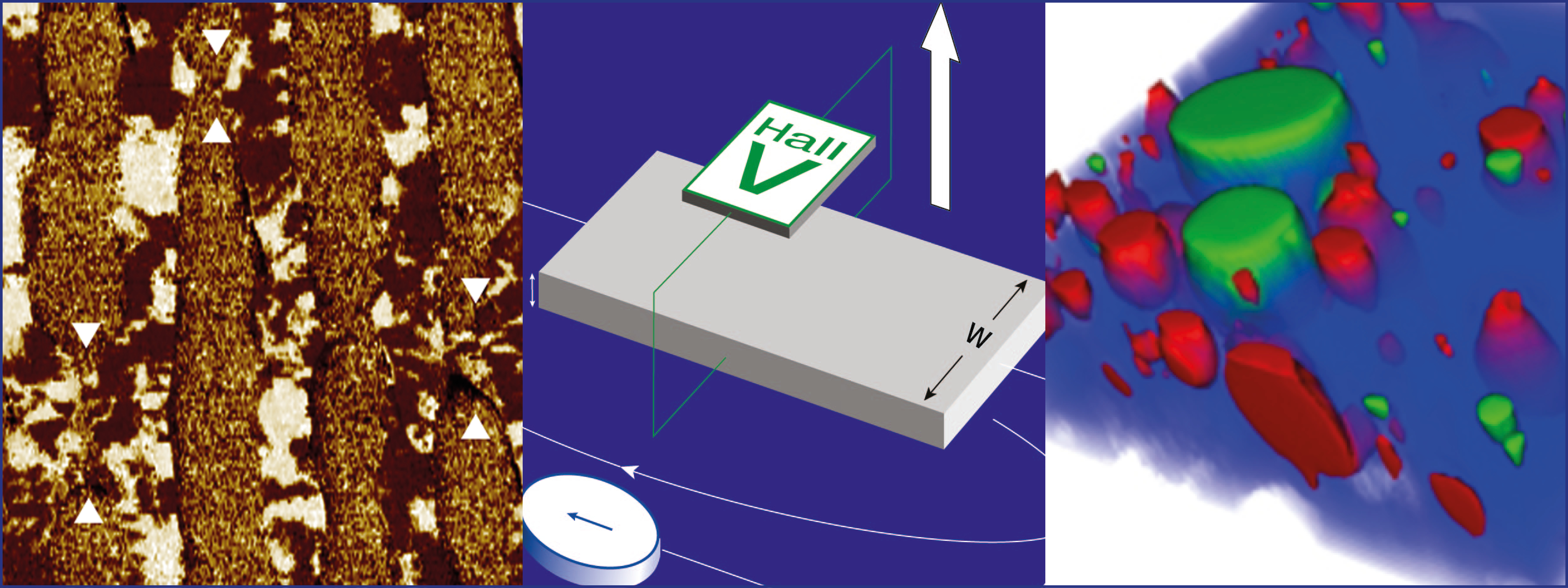
Piezoelectric force microscopy (PFM) is a form of scanning probe microscopy (SPM) that lets researchers image and manipulate piezoelectric and ferroelectric domains in materials. In this webinar, members of the technical-marketing team at Park Systems introduce the principles behind the technique, which involves engaging a sample surface with a sharp conductive SPM probe and then applying an AC current to the probe’s tip to deform the surface via a piezoelectric force. The PinPoint variant of PFM, specific to Park Systems’ atomic-force microscopes, lets you image samples with higher spatial resolution and with no lateral force. The webinar, PinPoint Piezoelectric Force Microscopy, also reviews the technique’s potential for investigating the electric domain structures (such as polarity) in piezoelectric and ferroelectric materials.

Atomic force microscopy (AFM) is a powerful tool in nanotechnology that has been widely used to study collagen, which is the most common protein in mammals and is found everywhere in connective tissues, including bone, skin, and muscle. Conventional techniques to characterize these fibrils are mainly based on AFM force-volume spectroscopy, which collects force-distance curves at each pixel to calculate material properties. However, these techniques are slow and it can take hours to acquire an elasticity map, which is one reason why Park Systems has developed the PinPoint Nanomechanical Mode. At least 100 times faster than traditional techniques, it can create a map in minutes, with a correlated topography image that reveals the position and orientation of the sample. In this webinar, In-Air and In-Liquid AFM Imaging with PinPoint Nanomechanical Mode, staff at Park Systems discuss this new mode, which can create quantitative maps of the mechanical properties of various materials, ranging from hard disks to soft tissues, including collagen fibrils.

Scanning ion conductance microscopy (SICM) is a variant of scanning probe microscopy (SPM) that allows researchers to determine the surface topography of samples at nanometre range in a non-destructive manner and under in situ conditions. Scanning electrochemical microscopy (SECM), meanwhile, is another SPM technique, this time letting you study the local electrochemical phenomena at various materials interfaces in liquids. SICM, which uses the increase of access resistance in a nanopipette placed in an electrolyte solution, monitors the ionic current flowing in and out of this probe – a flow that is hindered as the tip closes in on a sample surface. In SECM, in contrast, an electrode tip is used to acquire spatially resolved electrochemical signals over a region of interest, with the 2D raster-scan information yielding images of surface reactivity and information on the rates of chemical processes. In this webinar, Scanning Ion Conductance Microscopy (SICM) and Scanning Electrochemical Microscopy (SECM), applications staff at Park Systems explain the basics of both the techniques and discuss their applications in analytical chemistry and electrochemistry.

Material matters

Lake Shore logo

The Hall effect is not just a key phenomenon in condensed-matter physics – it’s also a vital way for characterising the material properties of semiconductors. In the 88-page Hall Effect Measurement Handbook white paper, Lake Shore senior scientist Jeffrey Lindemuth provides both new and experienced material researchers with a comprehensive guide to the theory of Hall measurements. It includes methods to measure the resistivity and the Hall coefficient of materials, major sources of measurement errors, ways to minimize the effects of these errors, and more besides.

Seeing molecules in 3D

WITec logo

Confocal Raman imaging is a powerful, versatile and ever-more common microscopy technique, which can quickly identify the molecules in a sample and visualize their distribution in 3D space. To find out more about this non-destructive and label-free chemical imaging method, which has big potential in many different fields, why not view the webinar The Analytical Power of Correlative Raman Imaging: New Developments, Tools and Applications by Miriam Böhmler and Ute Schmidt. As senior application scientists at WITec, they will introduce the basic principles of Raman microscopy, explain the associated hardware and software, and describe several of its variations – including relevant application examples. They then introduce correlative microscopy and provide details of Raman-AFM and Raman-SEM (RISE) microscopy too.

Microbe-killing short-wavelength UV radiation produced by LEDs

An array of low-voltage LEDs that emit short wavelength ultraviolet (UV) light could be used to kill harmful microbes on the skin and in the throat and nose – with minimal harmful side-effects to patients. The prototype device was developed by researchers at Germany’s Ferdinand Braun Institute and the Technical University of Berlin, who are currently testing its safety and efficacy.

Treating disease with antibiotics has led to the rapid evolution of drug resistant pathogens – which are believed to be responsible for about 700,000 deaths per year worldwide.  One emerging solution to this global health problem involves killing harmful microbes on skin and other living surfaces using short-wavelength ultraviolet light. Unlike the longer-wavelength UV light currently used to kill microbes on inanimate surfaces, this UV light travels a very short distance in skin. As a result, it cannot penetrate the dead upper layers of the skin to reach the living cells below. Any minor damage to skin that does occur is easily managed by the skin’s natural healing response – minimizing any harmful side-effects.

While short-wavelength UV light can be produced by LEDs, components are not widely available on a commercial basis because of various technological challenges. In their study, the FBH and TUB teams developed a prototype device that incorporates emerging LED technology. It features an array of 118 LEDs spread over an area of 64 cm2 and emitting UV light at a wavelength of around 230 nm. The setup delivered a maximum irradiation power of 0.2 mW/cm2 over an area of 36 cm2, with 90% uniformity.

Assessing DNA damage

The researchers will now assess the performance of their device using tissue samples of both skin and mucous membrane. The latter is the soft lining found in the nasal cavity and the back of the throat, which are both preferred habitats for many harmful pathogens. Through these tests, they hope to determine the extent of damage to DNA caused by varying doses of light. They will also compare the pathogen-killing effectiveness of the radiation compared with other UV light at other wavelengths.

The researchers believe their device promises to offer significant safety improvements on previous ultraviolet-based approaches, since the LEDs involved have low voltages, and convey little heat or strain to the skin. They hope their insights may soon lead to miniaturized devices which could be incorporated into endoscopes, allowing pathogens to be killed in small orifices, which are harder to access. Perhaps most importantly, it could also allow doctors to inactivate the SARS-CoV-2 virus responsible for COVID-19 inside the throat – the very spot where it first begins to replicate.

Making images with sound

Hovering 3D images are the stuff of science fiction. Just think of R2D2 projecting a message from Princess Leia in Star Wars, or perhaps Iron Man designing his latest tech in Marvel movies. Classics like Blade Runner and Back to the Future even had them in the background of shots as giant advertisements. But in a Faraday cage at the University of Bristol in the UK, fiction is becoming reality with the help of some speakers and polystyrene balls.

As I step into the windowless box that is part of the Ultrasonics and Non-destructive Testing Laboratory, it feels like I’ve walked into a shipping container. Research associate Tatsuki Fushimi (who has since moved to the University of Tsukuba in Japan) explains that he works in here not because he needs to block electromagnetic fields – which is what a Faraday cage is normally used for – but because being inside the sealed box cuts down on drafts that might knock his polystyrene balls out of the air.

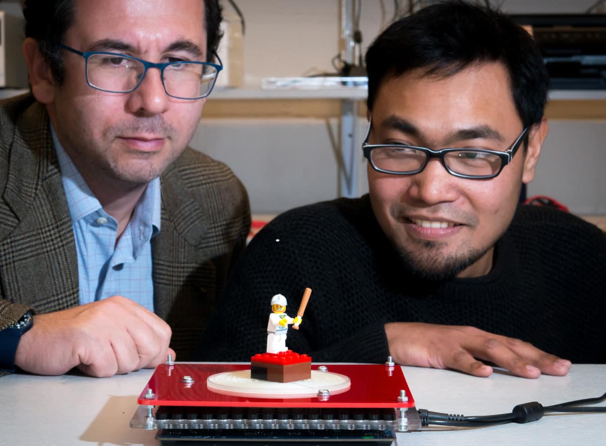
Fushimi then shows me what we have come to see: two horizontal grids of 30 miniature loudspeakers spaced around 20 cm apart and facing each other. The 10 mm-diameter speakers are the same as the ultrasonic transmitter and receivers used in car parking sensors. “You can buy them from – maybe not Amazon – but from normal electronic shops,” Fushimi says. After switching on his laptop, he picks up a tiny polystyrene ball, places it between the two transducer arrays and lets it go. And the ball just stays there, hovering, suspended in mid-air.

It starts with a tractor beam

The group at Bristol, and the Interact Lab at the University of Sussex in the UK, are at the forefront of the new field of “acoustic levitation” – essentially using sound to lift objects by counteracting the force of gravity with the pressure of acoustic waves. In 2015 a collaboration between the two groups unveiled a device known as a sonic tractor beam that could levitate objects and rotate and move them in multiple directions (Nature Comm. 6 8661). While similar types of levitation had been demonstrated before, previous attempts required particles to be surrounded by speakers in all, or at least most, directions. The difference with this new device was that it used just a single array of 64 loudspeakers, operating at 40 kHz.

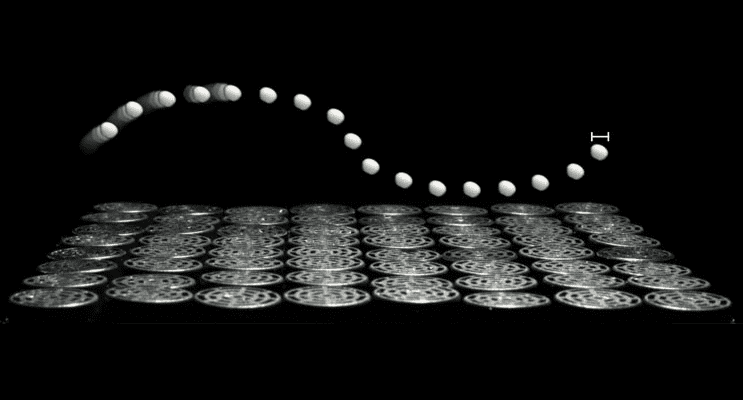
multiple photos of a levitating polystyrene bead

Controlled by a programmable array of transducers, the grid of speakers produced acoustic shapes out of high-pressure ultrasound waves that could surround and trap objects in mid-air and be adjusted to rotate and move them. The researchers created three different acoustic shapes with the sonic tractor beam: tweezers, a vortex that trapped objects at its core, and a cage. In each case they demonstrated that they could control polystyrene particles ranging from around 0.5 to 3 mm in diameter.

Since then, the field has progressed with various innovations. For example, in 2018 a team at the Interact Lab combined a larger array of 256 loudspeakers with an acoustic metamaterial – an engineered material with structural properties that do not usually occur naturally – to bend a beam of sound around an obstacle, and levitate and manipulate an object on the other side. This device was named SoundBender (UIST ‘18 10.1145/3242587.3242590).

Then later in 2018, Bruce Drinkwater, professor of ultrasonics in the Bristol group, and Asier Marzo, who is now based at the Public University of Navarre in Spain, unveiled an acoustic levitation device that used two arrays of 256 loudspeakers to levitate and individually manipulate up to 25 polystyrene balls (diameter 1–3 mm) at the same time (PNAS 116 84). The ability to create and adjust multiple acoustic traps simultaneously opened new possible applications for sonic tractor beams.

Soundbender

The persistence of vision

An early idea the Bristol researchers had was to create mid-air, hologram-like visual displays by using multiple levitated and illuminated polystyrene beads like they were pixels. But they found this approach didn’t work as well as they had hoped. The graphics created were poor and coarse because the beads had to be at least a wavelength apart (about 1 cm). And the more particles used, the less power there was to manipulate them individually.

The team therefore came up with another idea: trace the image with a single acoustically levitated and illuminated ball travelling at high speeds. Essentially, if you move the illuminated particle fast and precisely enough you can create the illusion of the picture. It’s all thanks to persistence of vision – the capacity of the eye to briefly maintain an image on the retina after it has disappeared, enabling successive images that follow rapidly after each other to be perceived as one.

If you move the illuminated particle fast and precisely enough you can create the illusion of the picture, thanks to persistence of vision

Fushimi says that the levitating particle is essentially a way of displaying the light needed to create the 3D image. “For light to be seen at each point you need something for it to be reflecting off. By placing this particle at a point in space you create like a voxel [a 3D pixel] in space. The question of how you make those voxels appear in mid-air was solved by using acoustic levitation,” he explains.

Back in the Faraday cage, Fushimi fiddles with his computer – which is connected to the arrays via a set of control boards and amplifiers – and the levitated polystyrene ball starts to trace out a circle in mid-air, changing colour as it is illuminated by a nearby multicoloured light. As the bead speeds up while circling continuously on the same path, it becomes blurred, and an image of the circle a couple of centimetres in diameter just about persists.

The polystyrene ball is now moving at 5 Hz, which, Fushimi explains, means that it travels around the circle five times a second. To achieve the persistence-of-vision effect “the minimum frequency that we need to move these particles at is 10 Hz”, he adds. If the ball was completing the circle 10 times every second, in theory a multicoloured image of a circle would appear in mid-air.

figure 1

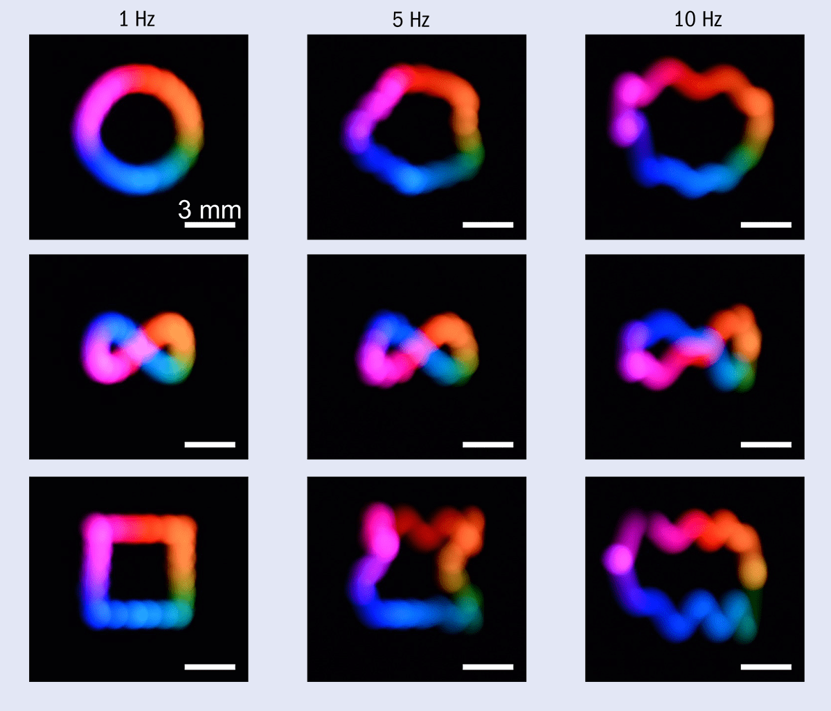
Unveiled last summer, this “acoustophoretic volumetric display” dramatically increases the speed and accuracy with which a 0.7 mm polystyrene ball can be manipulated compared with previous acoustic levitators (Appl. Phys. Lett. 115 064101). The particle can be positioned with an accuracy of 0.11 mm in the horizontal axis and 0.03 mm in vertical axis, while moving at a speed of 60 cm/s. With this device, the researchers can accurately trace out images such as a 12 mm2 replica of the University of Bristol logo, as well as simple shapes like circles, figure-of-eights and squares. They are not yet, however, able to create them fast enough to achieve the persistence-of-vision effect. To see the images, you need to use a camera with a slow shutter speed.

When the polystyrene ball in the Faraday cage hits a frequency of 10 Hz it does produce a circle that can be viewed as an image, but it is not a smooth circle – it has a wavy, squiggly outline (figure 1). But it does demonstrate proof-of-concept.

Bigger is better

A few months after the Bristol team’s work, researchers at Sussex’s Interact Lab, led by Sriram Subramanian, also unveiled an ultrasound-powered, 3D visual display (Nature 575 320). Their much larger device can produce a persistence-of-vision effect.

Armed with two arrays of 256 transducers, they demonstrated that they can move a polystyrene bead at speeds of almost 9 m/s. This allows them to draw 2 cm images of torus knots, smiley faces and letters in less than 0.1 s, which is fast enough for them to be visible to the naked eye. They can also create more dynamic content, such as a number countdown, and still achieve the persistence-of-vision effect. More complex images like 3D globes and the University of Sussex logo can’t be viewed with the naked eye and instead require long camera exposures to be seen properly.

Drinkwater says that the performance of the Sussex device is impressive. “The accelerations and speeds are so good, whereas the hardware is essentially the same [as ours], the only difference is it is bigger. The natural thing to think is that bigger might slow it down, but it doesn’t,” he adds.

He believes that the reason the larger device achieves higher speeds is because the particle is positioned further from the speaker arrays. This means, he explains, that the changes in the phase of the ultrasound required to shift the acoustic traps and the particle can be smaller. And if the phase changes are smaller you hit the limits of the loudspeakers at higher particle speeds. Fushimi says it is much like drawing an image on a wall with a laser pen. “If you are very close to the wall you have to move a lot to move the laser point from one end of the wall to the other, but if you are further away you only have to flick your arm a tiny bit.”

Subramanian says that this could be the case, as the distance between the acoustic traps in their setup is quite small. He adds, however, that the “devil is in the detail” and that he can’t speculate too much until he knows “exactly what [the University of Bristol team] tried and didn’t try, and how exactly they tried it”.

The Sussex researchers are now looking at how they can improve their hardware setup to build large and more complex displays, with faster moving particles. Currently, their acoustic levitation device is centrally controlled, with all the decisions being made on a computer before being sent to the control boards and loudspeakers. “We push the data to a USB port and on to these transducers,” Subramanian explains, “and quickly you start hitting the limits of how much data you can push through one USB port as you start increasing the number of transducers. You need to send amplitude and phase information for each transducer individually at very high speed.”

He sees solutions in making the system wireless – to enable faster data transfer – or less centrally controlled, with more computerization at the control boards and transducers. “So, you don’t send all the information from the PC, but you send some high-level information and each transducer board does the calculation locally,” Subramanian explains.

Subramanian hopes that introducing some intelligence in the transducers will also enable them to produce displays with multiple levitated particles acting as pixels, to create more complex and detailed images. “Our ambition over the next couple of years is to be able to have a talking head that is about the size of a normal human head,” he says (see box below).

Floating singing heads

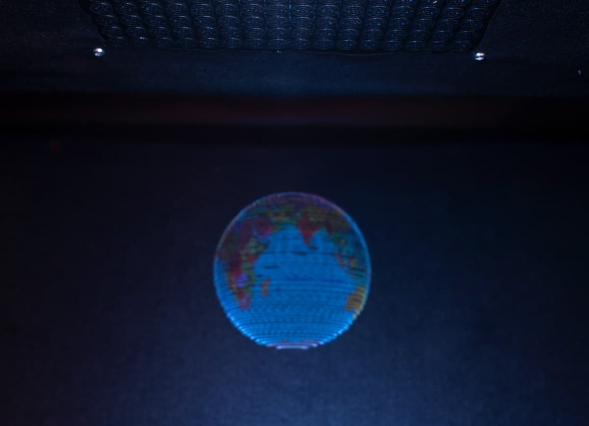
Ultrasonic globe

The Interact Lab at the University of Sussex, UK, has just started a project with the Shanghai Academy of Fine Arts in China, with funding from the UK’s Arts and Humanities Research Council. Their aim is to create public installations and displays in which sound is produced through acoustic levitation, with the focus initially on creating museum exhibits. “One of the first things we are trying to do is to create a gallery of talking heads,” says Sriram Subramanian.

He sees these as being heads of famous artists singing – such as a 3D moving image of Freddie Mercury’s face belting out the hits of Queen. And he thinks that the researchers will be able to get to that point in the next six to eight months, although they won’t be life-size singing heads, more likely 20% smaller.

With the current displays, the Sussex team can already produce audible sound. This is done by vibrating the levitating, polystyrene bead at audible frequencies, which is possible because the device uses different elements of the ultrasound signal for levitation and vibration. The ultrasound phase information is used to create the levitation traps, while amplitude modulation is used to generate audible sound. This, Subramanian says, is a cheap way of producing directional sound: “You get it free”.

“If you’re walking past these talking heads there would be no sound coming from them except when you stand and look at, say, the face of Freddie Mercury, then maybe he starts singing one of his songs,” Subramanian says. “And there is no separate speaker, it is the sound coming directly from the beads.”

Understanding the trap

Back at the University of Bristol, researchers are now working to develop more accurate models of the dynamics and shapes of the traps in the acoustic levitator. They hope that this will enable them to work out the limits of acoustic levitation and then explore its applications. “Levitating objects and moving them around is something that is useful for things other than acoustophoretic displays, such as holding samples, continuous production lines and a manner of other manufacturing concepts,” Drinkwater says. Manipulating pharmaceutical products, where contamination is an issue, would be a good example, he adds.

Drinkwater says that they have a simple model of the traps, which is not quite right but not far off. He explains that the system is like a dynamic trap. When the particle is in a node in the acoustic field, which ever direction it moves in, the force gets stronger, making the system stable and holding the particle in place. The particle moves with the acoustic trap, but as you move it faster the trap starts to resonate, and due to a lack of dampening in the system, it becomes unstable. And this is why the circle I saw in Fushimi’s lab loses its smoothness as its frequency is pushed to 10 Hz – the particle vibrates too much (figure 1).

Tom Hill, an expert in nonlinear dynamics at Bristol, says that you can imagine the polystyrene particle as a ball in a bowl. “If you have a ball in a bowl and you are trying to move the ball in a particular path, it is easy if you do it slowly, but as soon as you do it fast it starts sloshing around the bowl,” he explains. “It’s like we’ve got a bowl that is a really complicated shape and actually getting a model of what that shape is, is very, very difficult. Plus, as you move the bowl around it is changing shape and there are other complexities.”

However, the Bristol researchers believe they are nowhere near the inertia limit yet – the amount of force they can apply and the speed at which they can move the particle. Drinkwater says that part of the problem is that the loudspeakers they are using aren’t up to it and that is a big area for potential future research. He says that “the bigger display seems to be one way of sort of getting around that problem” – but adds that you will still eventually hit a limit and go back to “the wobbling around, the bowl problem”.

The aim, Hill says, is to understand the shape of the bowl and how it changes in space. Then you could model exactly how you need to move the bowl to move the particle along the desired path. “The interesting thing with that is it would give you a maximum speed – a fundamental limit to how fast these [levitated particles] can go,” Hill adds.

Drinkwater likens his acoustic traps to an invisible robot arm – they grab things and move them around. And, just like robot arms in factories, his traps could be used to manufacture things, as well as creating images. If he can improve his set-up so that lots of polystyrene balls can be packed into a small space and move quickly and accurately, who knows, perhaps we’ll start seeing the 3D levitating projections of science fiction in real life.

Entanglement gets hot and messy

Entanglement – a purely quantum-mechanical effect that allows two or more particles to have a much closer relationship than classical physics permits – can survive high temperatures and chaotic environments. This unexpected finding from researchers at the ICFO in Barcelona, Spain could mean that entanglement-based quantum technologies, which were previously thought to function only in cold, low-noise conditions, may work in “hot and messy” environments too.

Quantum entanglement is the process by which particles such as photons become inextricably linked, such that if one is polarized in a vertical direction, then the other will always be polarized in a horizontal direction. Hence, by measuring the polarization of one photon in the pair, we immediately ascertain the polarization of the other, no matter how far apart they are. Once thought to be a quirky – or even nonsensical – aspect of the quantum world, this “spooky action at a distance”, as Albert Einstein called it, is now being exploited in quantum cryptography and quantum communications systems as well as sensors used to detect gravitational waves.

Entangled states are usually thought of as being extremely fragile. Even the tiniest disturbance (or noise) in their environment can cause entangled particles to “decohere” through random interactions, making the entanglement disappear. Current quantum technologies therefore typically operate at ultracold temperatures, and their designers go to great lengths to keep their quantum systems isolated.

The opposite strategy

The ICFO researchers, led by Morgan Mitchell, have now shown that the opposite strategy – actively promoting random interactions – can help generate and preserve entanglement too. In their experiment, they heated a collection of rubidium-87 (87Rb) atoms to 450 K, creating a vapour of hot alkali atoms. They found that individual atoms in this vapour were not isolated but collided with each other every 20 microseconds. Each collision set their electrons spinning in random directions, producing a magnetization.

Mitchell and colleagues used a laser to monitor this magnetization via a series of measurements that enabled them to detect entanglement between the atoms and study the effect of the atomic collisions. The measurement technique is known as optical quantum non-demolition (QND) because it can measure the electron spins without disturbing them. “If a regular measurement is like a biopsy, in which material is taken and analysed, then a QND measurement can be thought of as like MRI, in which we obtain information without damaging the system,” Mitchell explains.

Singlet-type entangled states

While many different types of collisions between atoms are possible, the most frequent are collisions in which the atoms exchange electron spin. The researchers observed that a huge number of rubidium atoms – at least 1.52 × 10¹³ out of 5.32 × 10¹³ participating atoms – were entangled via these spin-exchange collisions and entered singlet-type entangled states. “These are a curious state of two spins: each spin seems to be completely random, pointing in every direction simultaneously,” explains Mitchell. “Nonetheless, the spins always point in exactly opposite directions. It is thus a state that is completely coordinated while also being totally random.”

In the QND measurement, the contribution from a singlet is zero, he adds. “Since they point in opposite directions, what is contributed by one spin is exactly cancelled by the other spin. So, when we see the optical QND signal becoming very ‘quiet’, we know that many singlets have formed.”

And that was not all. As the ICFO team describe in their paper, which is published in Nature Communications, they also observed that the entanglement was non-local, meaning that it involves atoms that are not close to each other. Between any two entangled atoms there are thousands of other atoms, many of which are entangled with still other atoms, in a giant, hot and messy entangled state, they say.

Sensing technologies could benefit

When the measurement is stopped, the entanglement persists for about a millisecond, explains study first author Jia Kong. This means that a new batch of 15 trillion atoms is being entangled 1000 times per second. 1 ms is long enough for each atom to undergo about 50 random collisions, clearly showing that the entanglement is not destroyed by these random events. “This is maybe the most surprising result of our work,” she states.

The findings will be important for sensing technologies based on hot, dense clouds of atoms. One such technology, known as vapour-phase spin-exchange-relaxation-free (SERF) media, operates at 450 K and is used in applications as diverse as magnetometers that can detect magnetic signals from the brain and instruments that look for signs of dark matter and physics beyond the Standard Model. “Whether or not entanglement could survive at these hot temperatures was an open question until now, but our experiments show that it indeed can,” Kong tells Physics World.

App for low-cost smartphones can diagnose malaria

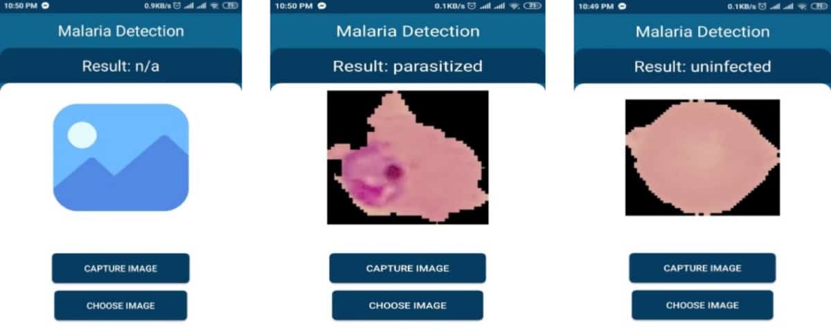
Graphical interface

A team of six engineers from the North South University of Bangladesh has developed a program that can automatically diagnose malaria using a smartphone presented with a segmented blood smear image. This approach has potential to overcome the need for expensive equipment and highly trained personnel for malaria diagnosis in resource-limited settings. If patient samples, so-called blood smears, are imaged using a mobile phone and microscope, then the app can analyse the images for the presence of malaria parasites.

Writing in the journal Diagnostics, the developers explain that “the model can work independently in the mobile app without needing Internet connection and can help an individual without any technical expertise to detect malaria parasites from the blood smear”.

The research team developed 10 computational models and evaluated their computational requirements, as well as their accuracy, precision, sensitivity and specificity. Some of the models were trained using autoencoder, a type of artificial neural network used to learn in an unsupervised manner how to detect patterns while disregarding noise. These autoencoder-trained models were the smallest in size at just 73 KB (less than Whatsapp). Such computational efficiency enables automatic diagnosis to be performed on low-cost smartphones.

The engineers

From computational heavy to lightweight

In 2019, engineers from the US had already developed a neural network that could achieve automatic malaria diagnosis. However, their model was too computationally intensive to work on smartphones or in a web browser. The new model by Faizullah Fuhad and his colleagues requires over 4 million times less processing capacity than the previous model while maintaining very high classification accuracy. The team from Bangladesh demonstrated functionality both offline on mobile phones, as well as online in a web application.

The researchers used a public dataset containing 27,558 images of red blood cells from 150 infected and 50 healthy patients to train the model. The images were taken by placing a smartphone on a conventional light microscope (available from approximately £100). Afterwards, the developers tested the model on a different public dataset, confirming the model’s robust performance.

The pros and cons of diagnosis methods

Currently, malaria can be diagnosed from clinical symptoms such as fever, or by polymerase chain reaction (PCR), rapid diagnostic test (RDT) or microscopy. As clinical diagnosis and PCR require laboratory settings, the other two methods, RDT and microscopy, are most commonly used for malaria diagnosis today.

RDT is a powerful tool, using a test strip similar to a pregnancy test. However, this method has some shortcomings compared with microscopy. It is less sensitive, more expensive and affected by heat and humidity. Also, RDT can neither quantify parasite density nor identify the species of parasite causing the infection. Microscopy is therefore the best available technique, but unfortunately requires highly trained personnel. The new smartphone app developed by Fuhad and colleagues should overcome this limitation.

Copyright © 2026 by IOP Publishing Ltd and individual contributors