Ancient rolls of manuscript that were carbonized during the eruption of Mount Vesuvius in 79 AD have been virtually unfolded by scientists in Italy. Having probed the “Herculaneum papyri” with X-rays, the researchers were able to isolate individual layers from the extremely delicate and heavily distorted rolls and identify Greek letters written on them. They are currently refining their technique and hope shortly to be able to read significant portions of the ancient text.
The Herculaneum papyri, discovered in the mid-18th century, were stored in the library of a huge villa overlooking the Bay of Naples that some think belonged to the father-in-law of Julius Caesar. Numbering more than 1800 and concerned, at least in part, with the work of the Greek philosopher Epicurus, the scrolls were carbonized and buried by volcanic material from Vesuvius. Although the eruption preserved the manuscripts for posterity, the high temperatures and pressures it generated also crushed and partially melted the precious texts.
Unrolling headache
Trying to unfold and read the very fragile and irregularly shaped scrolls has proved a major headache for scholars. Some of the best-preserved texts have been unrolled by mechanical techniques, but others have been partially or completed ruined. Meanwhile, many non-invasive techniques – such as multispectral imaging and X-ray fluorescence – are unable to penetrate the unrolled manuscripts and therefore cannot distinguish features on internal layers.
The latest work exploits a technique known as X-ray phase-contrast tomography (XPCT). Conventional X-ray tomography records the extent to which different materials absorb the radiation. But it is of little use when trying to distinguish different materials with very similar densities – such as the black carbon-based ink used to write on the papyri and the carbonized papyri themselves. XPCT instead relies on the X-rays’ phase changing as the photons takes different paths through a sample. The technique is sensitive enough to detect the variation in refractive index between a minute blob of ink and the papyrus surrounding it.
The Herculaneum papyri were first analysed using XPCT by Vito Mocella of the Institute of Microelectronics and Microsystems in Naples and colleagues. In 2013, they exposed two papyri from a collection in Paris to X-rays from the European Synchrotron Radiation Facility (ESRF) in France. As they reported two years later in Nature Communications, Mocella and team found they could identify segments of writing within the manuscripts. However, at that stage they did not attempt to virtually unroll the papyri.
Virtual handling
In the new research, presented on arXiv, physicists Alessia Cedola and Inna Bukreeva of the National Research Council Institute of Nanotechnology in Rome also used the XPCT technique at ESRF in 2016. Looking at two papyri from the National Library of Naples, they were able to combine their data-taking with a new way of virtually unrolling the scrolls. Rather than tracing out the geometry of individual papyri layers by observing the objects’ cross-sections, they instead used a 3D technique, which, says Cedola, allows them to study a larger portion of the text.
The researchers start by carrying out the digital analogue of traditional mechanical separation – they virtually remove a portion of a papyrus within a 3D tomographic reconstruction of the scroll. They then peel away the individual layers one by one, noting signs of any potential handwriting as they do so. If they do come across what appear to be letters, they flatten their virtual layer by adjusting its shape until the criss-crossed fibres that naturally make up the papyrus form a geometric grid.
Doing so, they have been able to identify several regions of potential text, the most extensive of which they reckon contains 14 lines of letters. Although many of the letters are yet to be deciphered, Cedola and co-workers nevertheless conclude that their technique has enabled “the most extensive potential textual portions ever read so far” from still-rolled Herculaneum papyri.
Deciphering challenge
Two “papyrologists”, also from the National Research Council in Rome, are working alongside Cedola and Bukreeva to decipher the text, having confirmed that it was probably written by philosopher and poet Philodemus, a follower of Epicurus. They hope to have completed their task by around the end the year. Then in early 2018, Cedola’s team plans to go back to Grenoble and investigate a number of papyri using a higher-resolution X-ray detector. Doing so, she explains, will allow them to better flatten the virtual layers and as such more easily remove unwanted shadows caused by undulations in the papyri. “We will be able to say with greater confidence what is a letter and what is shadow,” she says.
Mocella says that the latest research is “interesting work”, but maintains that it “doesn’t represent a significant advance” on his own group’s efforts. He adds that since publishing their initial results in 2015, he and his colleagues have been able to “virtually unroll some particularly large portions of papyrus on which we are currently improving the readability”.
Evidence for the extra space-like dimensions predicted by string theory could be found within Bose–Einstein condensates (BECs) – according to Sergio Gutiérrez, Abel Camacho and Héctor Hernández of Universidad Autonoma Metropolitana-Iztapalapa in Mexico City.
String theories and some other theories that try to describe physics beyond the Standard Model rely on the existence of extra dimensions. These dimensions are so small (about 10–35 m) that they have been impossible to detect, even by smashing particles together at the Large Hadron Collider or any conceivable future particle accelerator.
A BEC is an ensemble of ultracold atoms that are all in one quantum state – having a macroscopic wave function that extends across the entire ensemble. Writing in a preprint on arXiv, Gutiérrez, Camacho and Hernández point out that the wave function of the BEC would be confined within each extra dimension – much like the familiar “particle in a box” problem of quantum mechanics. This would result in a series of discrete energy levels, which would have an effect on the thermodynamic properties of the BEC.
Specific heat
The researchers reckon that the presence of extra dimensions could be revealed by measuring the discontinuity in specific heat that occurs when an ultracold gas of rubidium atoms condense to form a BEC. Studying this discontinuity as a function of the number of atoms in the BEC should point to extra dimensions, they say.
However, not all physicists are convinced. Writing on her Backreaction blog, Sabine Hossenfelder of the Frankfurt Institute for Advanced Studies points out that an enormous amount of energy would be needed to populate the discrete energy levels associated with the extra dimensions. As a result, she says, there should be no discernible effect on the thermodynamic properties of the BEC.
Optical solitons have been generated by firing an intense, ultrashort laser pulse into an optical fibre with a liquid core. The laser pulse interacts with the liquid and is converted into pulses of broadband infrared light (solitons) at wavelengths of 1.1–2.7 μm. Producing infrared solitons had proven difficult in the past and liquid-filled fibres could prove useful for providing broadband infrared light for medical imaging, metrology and spectroscopy.
The work was done by Mario Chemnitz and colleagues at Leibniz Institute of Photonic Technology, the Fraunhofer Institute of Applied Optics and Precision Mechanics, the Friedrich Schiller University of Jena, and the Helmholtz Institute Jena.
Molecules line up
The team used a hollow silica fibre that is filled with carbon disulphide, which is a liquid with a very large index of refraction. When a polarized infrared laser pulse is fired through the core, it begins to align the carbon-disulphide molecules along a specific direction. This modifies the optical properties of the liquid and therefore the propagation of light in the fibre.
An important feature of carbon disulphide is that the molecules are relatively slow to align themselves with the laser pulse. In their experiments, Chemnitz and colleagues used a laser pulse that lasted about 460 fs, which is much shorter than the time it takes the molecules to line up. According to Chemnitz, this delay results in an “optical memory effect” that has a desirable influence on the dynamics of the solitons. In particular, it reduces fluctuations in the bandwidth of the solitons, which means that the liquid-core fibre is a more stable source of broadband light than solid optical fibres made from special glasses.
Alternatives to the lithium-ion battery (LIB) become increasingly necessary as the demand for portable electronics, electric vehicles and grid-level energy storage technologies continues to develop. Current Li-ion chemistries are toxic to the environment, highly flammable, and will grow in cost as material needs increase. Instead, researchers are exploring new battery technologies such as aluminium ion-based systems, which have the potential to deliver the enormous capacities and high current capabilities necessary to power a sustainable future. Now, scientists at Clemson University in the US have built a prototype Al-ion battery (AIB) that uses a graphene electrode to intercalate tetrachloroaluminate (AlCl4–). The researchers have used the device to investigate the effect of defects and doping on battery performance.
Aluminium-ion batteries are increasingly considered as a possible alternative to Li-ion battery systems, but so far the element has been difficult to study. Unlike in LIBs, where the mobile ion is Li+, aluminium forms a complex with chloride in most electrolytes and generates an anionic mobile charge carrier, usually AlCl4– or Al2Cl7–. Writing in Nano Energy, Anthony Childress and colleagues at Clemson University’s Clemson Nanomaterials Institute have elucidated the intercalation mechanism of the AlCl4– anion in graphene electrodes, and provided a unique insight into the influence of defects and doping on the intercalation process.
Controlling graphene’s properties
Introducing defects into graphene has previously been shown to shift the Fermi level of the material, which corresponds to the cell potential of the battery. It has also been observed that the introduction of pores can facilitate access to the inner volume of the cathode, allowing ions to move in and out quickly for fast charging.
To investigate these factors, the Clemson group formed few-layer graphene (FLG) by decomposing methane on nickel foam at high temperatures. The presence of defects was controlled by sintering the pristine FLG with argon plasma. Alternatively, different levels of nitrogen dopants were introduced by adding a nitrogen precursor during the original deposition process. After they dissolved the nickel foam, the researchers were left with either pristine or modified graphene.
Understanding the battery performance
The team constructed batteries with aluminium anodes, pristine or modified FLG cathodes, and an ionic liquid with AlCl3 salt as the electrolyte. With pristine FLG as the cathode, the battery achieved a capacity of over 70 mAh/g for 1000 cycles. Although such a capacity is modest compared to modern Li-ion batteries, which typically store about twice the charge, the performance was impressive considering the extremely high charging/discharging rates that were achieved, with a full charge–discharge cycle taking less than three minutes.
The researchers attribute the exceptional reversibility they observed in this system to the robustness of the pristine FLG. When the FLG with induced defects was tested in a battery, the researchers found that it did not perform well at high current rates, since the defects resulted in poor interconnectivity of the FLG sheets at the edges, and inhibited electron transfer during fast cycling. The introduction of nitrogen doping resulted in a significant decrease in intercalation, and caused chlorine gas to be produced. The team speculate that the presence of nitrogen in the FLG induces some catalytic activity, liberating chlorine from the electrolyte.
The intercalation and deintercalation of AlCl4– in FLG were monitored by Raman spectroscopy, and the researchers found that FLG was electron-donating during the charge process. They then performed density functional theory (DFT) calculations to describe the interaction between the AlCl4– anion and the carbon layers. This model resulted in a slightly distorted AlCl4–tetrahedron, which is indicative of the anion accepting approximately one electron, and provides a very strong agreement between the observed Raman measurements and the DFT modelling.
This work informs the successful design of AIBs with graphene, and demonstrates that this battery configuration can perform very well over 1000 cycles at high rates of charge and discharge. The researchers also provide a fundamental insight into the intercalation/deintercalation of the AlCl4– anion in FLG. Further high-quality investigations of AIB chemistries such as this one will bring us closer and closer to a sustainable energy storage technology.
Details of the research can be found in Nano Energy.
Contrary to traditional thinking that the atmosphere drives sea surface temperature and surface heat flux variability in the mid-latitudes, researchers from the US have shown that where surface temperature gradients are strong, the ocean drives this variability. The finding highlights the importance of resolving internal oceanic processes as well as atmosphere-ocean interactions in models.
Stuart Bishop from North Carolina State University and his collaborators at the National Center for Atmospheric Research showed that in regions away from these strong mean sea surface temperature gradients, the traditional idea of atmospheric forcing still holds.
Oceanic weather drives the surface temperature variability of the Western Boundary Currents and the Southern Ocean Antarctic Circumpolar Current, particularly the Agulhas Return Current, Bishop and the team found. By dampening the sea surface temperature anomalies generated by eddy stirring using spatial and temporal smoothing, they showed that the oceanic influence on sea surface temperature variability increases with time scale but decreases with spatial scale. These regions transition from ocean- to atmosphere-driven at spatial scales less than 500 km, but this figure varies widely geographically.
This result is in contrast to previous work, where the mid-latitude sea surface temperature variability was atmosphere-driven and the ocean was passive. Many of these earlier studies, however, used rather coarse resolution observational estimates of sea surface temperature and surface heat flux, or coarse coupled global climate models. So ocean eddies were not resolved – the researchers involved noted this limitation, finding their results only applicable to regions away from strong oceanic currents.
Many scientists feel it’s important to understand ocean-atmosphere energy exchange and to capture it in climate models, to represent both the mean state and variability of the climate system accurately. This study highlights the value in precise and detailed observational estimates as well as the importance of using eddy-resolving models to simulate ocean-atmosphere interaction, especially in regions with strong sea-surface temperature gradients.
The researchers used state-of-the-art surface heat flux and ocean temperature observational estimates. A simple energy balance model of coupled air-sea interaction and a lagged correlation between ocean temperature and surface heat fluxes helped discriminate between atmosphere-driven and ocean-driven variability.
Who inspired you to study physics? Perhaps you had a great teacher or a supportive parent. But how might it feel if you’ve got a sibling who’s also into the subject? Would they be your rival or would the two of you support and nurture each other?
These issues facing “sibling scientists” are the cover feature of the August issue of Physics World magazine, which is now out. Turns out that sibling scientists are generally a force for good, especially with the elder child acting as a mentor and guide – often providing information, support and advice to the younger sister or brother.
I wonder in fact if we should do more to encourage boys and girls who are already in thrall with physics to persuade their siblings into the subject too. Of course, our feature isn’t an exhaustive scientific study, so do tell us if you know of other examples of sibling science.
Remember that if you’re a member of the Institute of Physics, you can read Physics World magazine every month via our digital apps for iOS, Android and Web browsers.
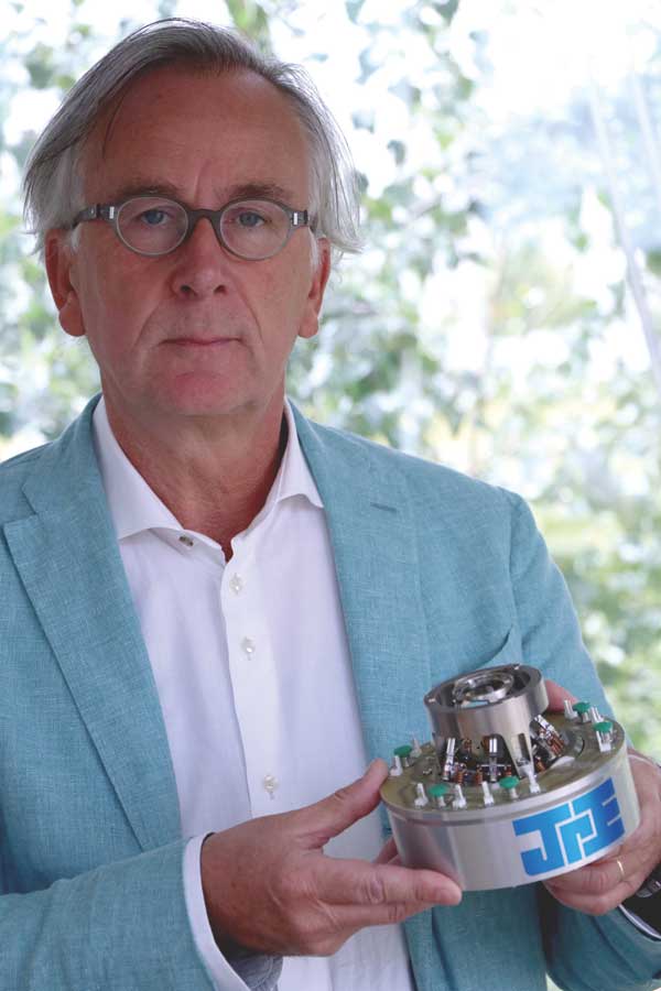
Ability to adapt: Huub Janssen. (Courtesy: Janssen Precision Engineering)
What led you to start Janssen Precision Engineering (JPE)?
I did my degree in mechanical engineering at the Eindhoven University of Technology in the Netherlands, and directly after finishing my studies I worked for a couple of large companies – first for ASML, which makes machines for the fabrication of transistors and silicon wafers, and then for Philips in its liquid-crystal displays business. At Philips, I was responsible for the equipment in two factories, and I did that for about six or seven years, but then a big reorganization within the company meant that the most advanced of the two factories I worked on was going to be closed. This implied that the majority of the interesting work I did would fall away because the other factory was really old-fashioned, so that helped convince me to go for a new challenge. Also, when I was still working for Philips, they asked me to set up projects for external companies, and I thought, “Okay, if I can do this within Philips, I can also do it on my own.”
How did you get funding for the business?
I had some savings, of course, but I didn’t get any external funding, and I also had no orders when I started – I really had to look for customers. However, if you are starting a project-based company there’s not a huge investment involved in finding a desk with a computer where you can do mechanical drawings, and a small space to organize and build mechanical and electronic parts.
How has JPE changed over the years?
Initially, I did project work for semiconductor companies that wanted to move instruments and machines very precisely, in the sub-micron and nanometre range. That was 26 years ago. At that time, I was designing components that could operate in an ambient environment, rather than for vacuum or cryogenics. But maybe 15 or 20 years ago, the semiconductor industry began to shift to a vacuum environment. This was a new challenge, and I like technical challenges. Then, several years later, I got a request from a client in astronomy who wanted a mechanism that would work at cryogenic temperatures, in a liquid-nitrogen environment. We had no experience with those conditions, but we had a brainstorming session, came up with a concept and discussed this with the client. Their reaction was, “Okay, that could work, but we would like to see a proof of concept.” So we built a demonstration unit, proved that it worked at low temperatures, and then went on to develop a complete instrument called a Configurable Slit Unit for the Gran Telescopio Canarias. It’s a kind of diaphragm where you move a mask to block certain stars from the sky, and you can use a computer to change the mask position. It’s a very complex instrument, with lots of actuators and sensors operating in a vacuum and cryogenic environment.
That project took us more than 10 years, with some stops and milestones in-between, and during that time we got a request from scientists who had read that we had experience of positioning objects in cryogenic temperatures. But we had been working at 80 K and they wanted something that would work at 4 K. Well, we never say no! And since then we have been getting more and more requests in that area. A lot of physicists are struggling with instruments in a cryogenic environment – it’s really technologically challenging, so we try to come up with solutions that are at least one step ahead of what people can buy off-the-shelf.
Have you had any significant setbacks? If so, how did you get past them?
As you may know, the semiconductor industry is very cyclical – it has ramped up and ramped down at least three or four times in the past 20 years, and it does it in an extreme way. At times, semiconductor companies will not outsource any work at all, or very little, and then at other times the ramp-up is incredible. You need a lot of flexibility, but you can’t really say to your employees, “Okay, now I need to employ two people, but later I will need 20 or 30.” So I have to find other interesting work, maybe even unpaid work, to give them during the down periods.
Did one of those downturns help lead you into scientific instrumentation?
Yes, I think that’s a good point. You need a mixture. In astronomy, most projects are long-term (sometimes even too long-term, in my view), so the phasing is different from the semiconductor industry.
Any advice for someone thinking of starting their own company in this field?
In this field, I would say that you have to start with a good product, by which I mean you need to make a technological breakthrough in a place where people need it. So I don’t think you should take an instrument that is already on the market and try to improve it, because there is very little chance that you can beat a competitor who already has their product and market organized. But technology breakthroughs alone are not sufficient. They may be enough to get started, but then you have to be aware of the market potential and get it well aligned with your product. Otherwise you will not earn back the money you spent developing it.
Space is not a friendly place for instruments to operate. Cosmic radiation fries their electronics; they have to cope with extreme variations in temperature; and for missions venturing close to the Sun, the solar wind can gradually erode their exposed optical surfaces. Consider Solar Orbiter, a European Space Agency mission designed to observe the Sun from relatively close quarters. The spacecraft’s elliptical orbit will periodically take it to within 42 million kilometres of the Sun, where it will reach temperatures as high as 790 K. A sunshield will provide some protection, but Solar Orbiter’s 10 instruments – including an ultraviolet spectrometer called SPICE (Spectral Imaging of the Coronal Environment) – will still have to cope with intense heat. Furthermore, several of these instruments need to be actively chilled to as low as 213 K.
Some planetary environments are even harsher. Venus, for example, has a surface temperature of 730 K, a surface pressure nearly 90 times higher than Earth’s, and a corroding, acidic atmosphere. Only a handful of spacecraft have ever successfully landed there, and those that did survived only a few hours inside bulky pressure vessels before succumbing to the unforgiving conditions. If we want to send spacecraft there again, we will need to find alternative solutions.
The combination of several different extreme conditions poses tough challenges for instrument designers. However, careful planning, design and testing can minimize the hazards, while ingenious modelling can help scientists and engineers identify potential problems early. For example, one of the most important tasks at the beginning of Solar Orbiter’s design phase was to develop a thermal model of the spacecraft. This model indicates which parts of the spacecraft become hottest, which parts remain coolest and which areas can safely be used to shed heat. The thermal models for each of the instruments on a spacecraft must complement all of the others, as well as the craft’s overall thermal profile. Care has to be taken to ensure that one instrument does not shed excess light and heat in a way that warms its neighbours. Only when this is achieved is it possible to begin building the instruments. “It’s a high-risk business, so you have to show feasibility right from the start,” says Martin Caldwell, an instrument designer at the UK’s Science and Technology Facilities Council’s RAL Space, where SPICE was built and tested. “No instruments get designed or built without knowing they are going to survive.”
Hiding from the heat – or not
Several techniques exist to boost instruments’ chances of surviving harsh environments. Most of the instruments on Solar Orbiter, for example, sit behind a 3.1 × 2.4 m sunshield built from multiple layers of insulation foil sandwiched between two black-plated surfaces. The instruments can’t hide from the sunlight entirely, of course, because they need to make observations, so the shield contains small doors leading to feedthroughs that allow sunlight into the instruments. Because the shield itself can expand with heat, these doors are deliberately oversized so that lines of sight to instruments are not blocked.
SPICE is designed to allow 30 W of sunlight to enter via its feedthrough. Light then strikes its main mirror coated with boron carbide, which reflects ultraviolet frequencies onto the instrument’s diffraction grating and then onto its detectors. Visible and infrared frequencies, which carry much of the heat, pass straight through the mirror and back out into space. In this way, the mirror and its exit path to space help to cool the instrument “passively”, as opposed to “active” cooling, which is typically provided by louvers or radiators filled with liquid helium. “It’s amazing how, with just passive cooling, you can get very different temperatures around a spacecraft,” says Caldwell.
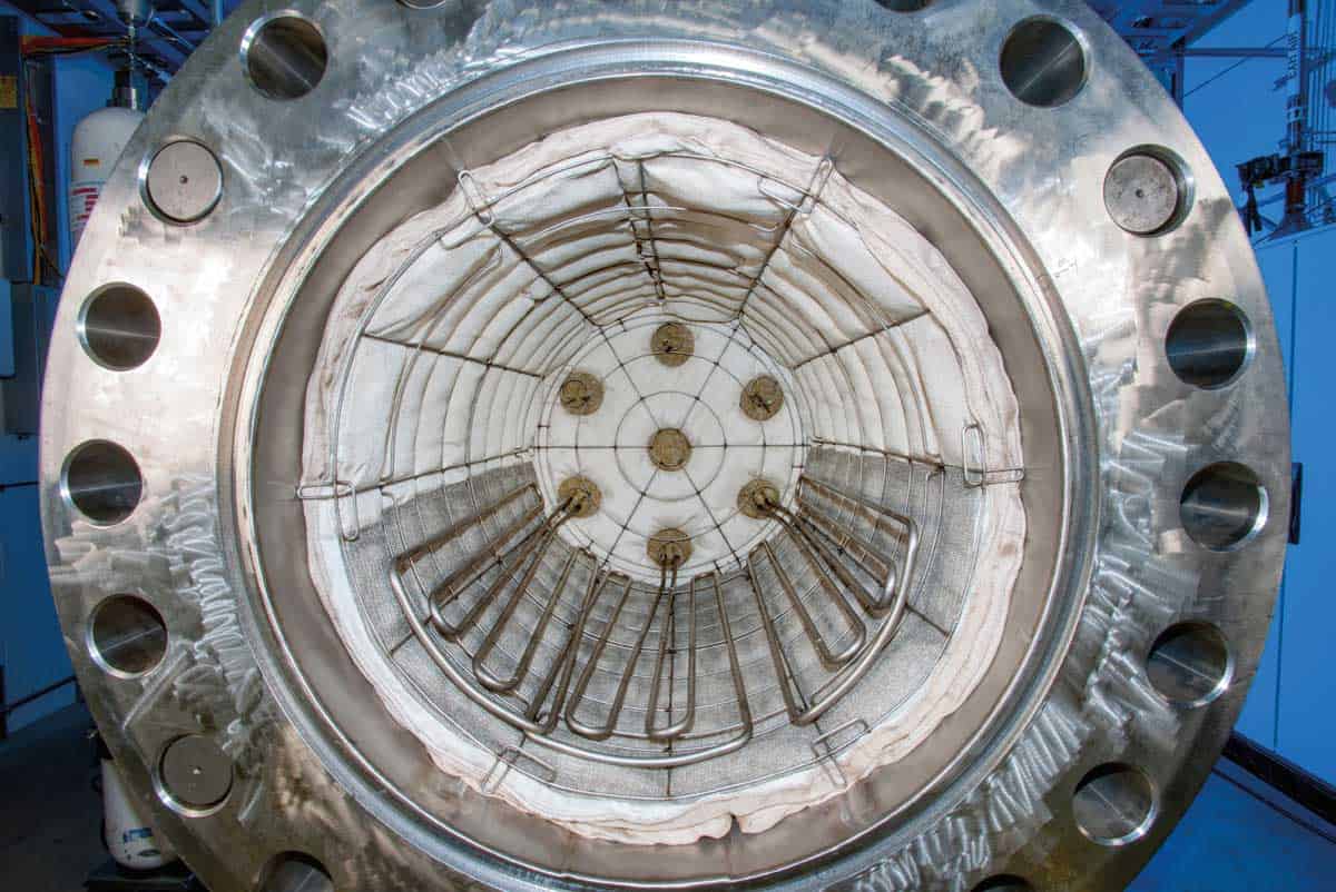
Controlled environment: Inside the GEER chamber at NASA’s Glenn Research Center. (Courtesy: NASA Glenn Research Center)
What happens when there is no way of hiding from the heat, like on Venus? The short lifespan of previous landers has helped dissuade space agencies from sending more such craft to its surface, but that could be about to change. Scientists working at NASA’s Glenn Research Center have developed new circuitry that could potentially survive for months, if not years. Electronics built from the semiconductor silicon carbide (SiC) have been in use on high-power devices for some time now and are well known for operating at high temperatures. However, says Philip Neudeck of the Glenn Research Center, what most people consider “high temperature” is only around 400 K to 520 K – still a far cry from Venusian conditions”. “There have been much briefer prototype demonstrations of silicon-carbide electronics at Venusian temperatures, but what hadn’t been demonstrated, until our recent work at NASA, is their long-term durability, especially within Venus’ atmospheric chemistry,” he explains.
Neudeck’s team has shown that SiC electronics have what it takes to survive on Venus. After building a test model with an integrated circuit chip containing just 24 transistors, Neudeck’s group used the Glenn Extreme Environments Rig (GEER) to simulate Venusian conditions and put the SiC electronics through their paces. This 1.2 m long stainless-steel chamber has a volume of 800 litres and can simulate not only the pressure and temperature on Venus, but also the 10 most abundant chemical constituents of the planet’s corrosive atmosphere with an accuracy down to mere parts per million. The rig can also be adapted for other environments, including those in the atmospheres of Jupiter and Saturn, and it can achieve even higher pressures than those found on Venus, albeit at lower temperatures. In a way, it’s the reverse of a vacuum chamber.
No instruments get designed or built without knowing they are going to survive
Martin Caldwell
“It’s no small feat to replicate those conditions on Earth, especially inside a chamber this size,” Neudeck says. His group had access to the GEER chamber for a straight run of 21 days and at the end the SiC electronics were still operating at full capacity. In comparison, the current record survival time on Venus is a mere two hours and seven minutes, achieved by the Soviet Union’s Venera 13 probe in 1982. The ultimate aim, Neudeck says, is to develop more complex electronics that can function indefinitely.
Thermal vacuum testing
At RAL Space, testing is also carried out in vacuum chambers built on a similar scale to the GEER. The chambers at its facility in Oxfordshire range from 0.5 m in diameter to a 5 m diameter chamber recently built by the Dutch company Schelde Exotech and designed specifically for instrument calibration testing. A second 5 m diameter, 6 m long chamber is being manufactured by the Spanish firm Cadinox, which won the tender from Added Value Solutions, a Spanish firm that has offices near RAL Space. Several even larger vacuum chambers, up to 8 m in diameter, are also being considered for the future, according to Giles Case, manager of the assembly, integration and verification facility at RAL Space.
Such large vacuum chambers are “pretty bespoke”, Case says. The specifications for chambers intended for spacecraft and instrumentation testing can vary, he explains, but in general they are constructed from electro-polished stainless steel that reduces outgassing. Beyond that, individual specifications may include how much weight it can carry, how many instruments can be adorned within it and how many doors and viewing points it has. A 5 m vacuum chamber costs around £10m, Case says, and the high cost is one reason why there are only around 10 large facilities for testing spacecraft and their instruments in Europe. By expanding their vacuumchamber capability, he argues that RAL Space will help enable the UK to “access the wider space market”.
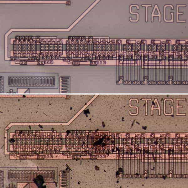
Tough tech: The integrated circuits made from silicon carbide before they entered the GEER test chamber (top) and after spending three weeks inside it (bottom), when they were still operating at full capacity. (Courtesy: NASA)
Final testing in a vacuum chamber can take weeks, as it did for SPICE in March and April 2017. Once inside the chamber, SPICE was mounted on a platform that acts as a temperature interface, controlled by a black-painted thermal shroud that surrounds the instrument under testing. In addition to a bright lamp to simulate sunlight, the temperature interface mimics the operating temperatures that SPICE will experience in space. This set-up is capable of producing temperatures as low as 93 K or as high as 373 K. SPICE was tested at 350 K – 20 degrees higher than its intended operating temperature.
Setting an instrument up inside a vacuum chamber is complicated, so to save time and effort, Caldwell explains that thermal tests are generally conducted alongside other performance trials. For SPICE, those tests include an ultraviolet test with a narrowband lamp to ensure the instrument was correctly calibrated and focused (some of SPICE’s ultraviolet testing had previously also taken place at the Metrology Light Source in Germany). There’s also a shake test and a long bake-out to clean the instrument. The vacuum chamber itself had to be extremely clean because even the smallest amount of organic molecules sticking to the optics could cause darkening when exposed to ultraviolet light. To that end, the instrument had to undergo constant gas purges to keep the optics clear of contamination.
It’s amazing how, with just passive cooling, you can get very different temperatures around a spacecraft.
Martin Caldwell
When the testing is finished, an instrument typically remains in the chamber while the observing ESA specialists analyse the results. “Very often they might want extra measurements,” Caldwell says. “So it makes sense to keep it in there until we’re ready for delivery.” After a month inside the chamber, SPICE was delivered to Airbus in Stevenage where, on 21 May 2017, it was mated to Solar Orbiter’s spacecraft structure – the culmination of five years’ worth of development at RAL Space. Once the other instruments are added, the entire spacecraft will undergo final thermal testing inside a vacuum chamber to compare with the previous testing performed on the earlier thermal model. If all of the results check out correctly, the orbiter will blast off from Earth and head towards the Sun in October 2018.
Revise and adapt
Neudeck also has big plans for 2018. By then he hopes to be testing heat-tolerant SiC electronics that have 10 times more transistors than the first prototype, which is roughly the same electronic complexity as the integrated circuits aboard early solar-system missions such as the Pioneer and Viking probes. However, that doesn’t necessarily mean a new Venus mission is on the horizon. Echoing Martin Caldwell’s warning that space is a high-risk business, Neudeck emphasizes the need to minimize that risk by subjecting the instrumentation to considerable scrutiny. “We first have to critically evaluate, improve and understand the technology, and be able to produce and qualify it in sufficiently large testing volumes, before we can actually fly it,” he says. “But there’s no doubt we are laying the path.”
Commercial interests could help accelerate development in this area. Aerospace companies are interested in using Neudeck’s technologies for sensors that sit inside the hot areas of jet engines to monitor and control the rate at which fuel is burnt. Additional interest comes from the energy and automotive industries. “We’re looking to leverage these commercial interests to get these electronics to Venus faster,” says Neudeck.
SiC electronics could potentially also find other space-based uses. In addition to coping with very high temperatures and pressures, the electronics should also theoretically exhibit some resistance to radiation, although tests still need to be conducted to prove and quantify the radiation advantage. If it can be proven, though, then it could ultimately make it possible for spacecraft to explore the environment around Jupiter’s harsh radiation belts. As recently as October 2016, NASA’s Juno probe suffered a glitch as radiation damaged its onboard electronics, causing it to miss an opportunity to take data during a close fly-by of Jupiter. SiC electronics might not only let spacecraft survive around the giant planet, but also permit deeper ventures into its atmosphere.
When it comes to high-risk environments in space, borrowing from what has come before can sometimes be the safer option. “One of the things that made Solar Orbiter possible was learning from the BepiColombo spacecraft,” Caldwell says, referring to ESA’s upcoming Mercury mission, which will also launch in 2018, but which has been in development for longer than Solar Orbiter. “In the space business, everybody is desperate to rely on things that have been done before, that are available and safe to use,” he adds. However, as the SiC electronics show, sometimes the old technology simply isn’t good enough. In those cases, instrument designers must start again, and reinvent a better, tougher wheel.
Helium is the second-most common element in the universe, but here on Earth it is classified as a scarce and non-renewable resource. It is also much in demand, with applications including medical cryogenics (as of 2016, around 30% of helium consumed in the US went to equipment such as MRI scanners), arc welding, leak detection and superconductivity. The combination of scarcity and high demand has pushed prices skyward: the price of grade-A helium (refined to 99.997% purity) has risen by around 175% over the past 10 years, to $7.21/m3, and even crude helium is now worth around $3.75/m3 – 30 times more than the equivalent volume of crude methane.
In many markets, numbers like these would make investors salivate. Yet so far, all helium-rich fields have been discovered accidentally by companies searching for petroleum. This lack of intent has contributed to a great deal of wastage: we know that many natural gas production companies are unwittingly venting helium, either because they fail to recognize the value of this minor component or because they are unaware of its presence. Indeed, our discovery of one such case produced the idea for our current research project.
A helium-prospecting industry powered by people who understand both the economic value of this rare material and how to explore for it. But when oil and gas companies prospect for petroleum, they benefit from a well-developed exploration strategy that helps them assess a new basin or area in a systematic way. Unfortunately, there is currently no equivalent methodology for helium.
My colleagues and I are seeking to address this gap in our knowledge. In a joint research venture between Durham University and the University of Oxford in the UK, with the financial support of the Norwegian state oil company Statoil, we have used well-established hydrocarbon exploration protocols as a template to develop a similar strategy for helium. This work has enabled us to begin to answer questions about how and where helium is generated; how it is released from potential source rocks; how it then travels significant distances from source rocks to potential traps; and how helium-rich gas accumulates in the shallow crust, as well as how these accumulations can be destroyed by natural processes. The project is still in its early stages, but we believe our research is an important step towards diversifying the helium supply, so that when another supply crisis occurs, we are better prepared.
Know your helium
There are two stable isotopes of helium: ubiquitous helium-4, which constitutes 99.999% of helium gas, and rare helium-3. Helium-3 is used in neutron detectors and is also a candidate fuel for power generation though nuclear fusion. It is often referred to as “primordial helium”, since the bulk of it was trapped in the Earth’s mantle during the planet’s formation. The more common isotope, helium-4, is mainly produced by the alpha decay of uranium-235, uranium-238 and thorium-232 in the Earth’s crust, which has led to it being called “radiogenic helium”.
Different rock types produce varying amounts of helium-4, controlled by the original concentrations of uranium and thorium and the age of the rock. Some of the highest accumulations of helium are found in large, stable continental blocks known as cratons that formed in the early Precambrian (up to 4.28 billion years ago), such as the Canadian Shield. Helium is found in many other geological systems, including groundwater, ancient brines, fluid inclusions in ore deposits, hydrothermal fluids, igneous intrusions and rocks, oil-field brines, lakes, ice sheets, oceanic sediments and coal measures. To date, however, only a few natural hydrocarbon gas fields contain helium in sufficient concentrations for its extraction to be considered commercially viable.
The first economic quantities of helium were discovered in 1903 in Dexter, Kansas, US. Analyses of this gas – which was initially referred to as “wind gas” because it was non-flammable – found that it contained approximately 82.7% nitrogen and up to 1.84% helium by volume. This concentration of helium was unusually high, as most natural gas fields contain helium only in trace amounts (≤0.05%). Significant discoveries in eight other US states soon followed, with some of these fields containing up to 10% helium by volume – significantly above the threshold at which helium is considered economically extractable (0.3%). Helium reserves have also been found in Algeria, Canada, China, Germany, Hungary, India, Kazakhstan, Pakistan, Poland, Qatar, Romania, Russia and the Timor Sea. However, none of these new helium reserves currently match the concentrations, number of occurrences or estimated reserve volumes associated with the older US fields.
Finding new sources
From a simplistic sourcing perspective, older rocks will generally have had more time to produce and accumulate helium than younger ones. Therefore, a logical first step in a helium exploration protocol is to identify viable Precambrian-aged crystalline terrains in areas that have remained relatively tectonically stable for long periods of time. However, age is not the sole determinant of a viable source rock. The helium also needs to have been released from the rock – a process known as primary migration.
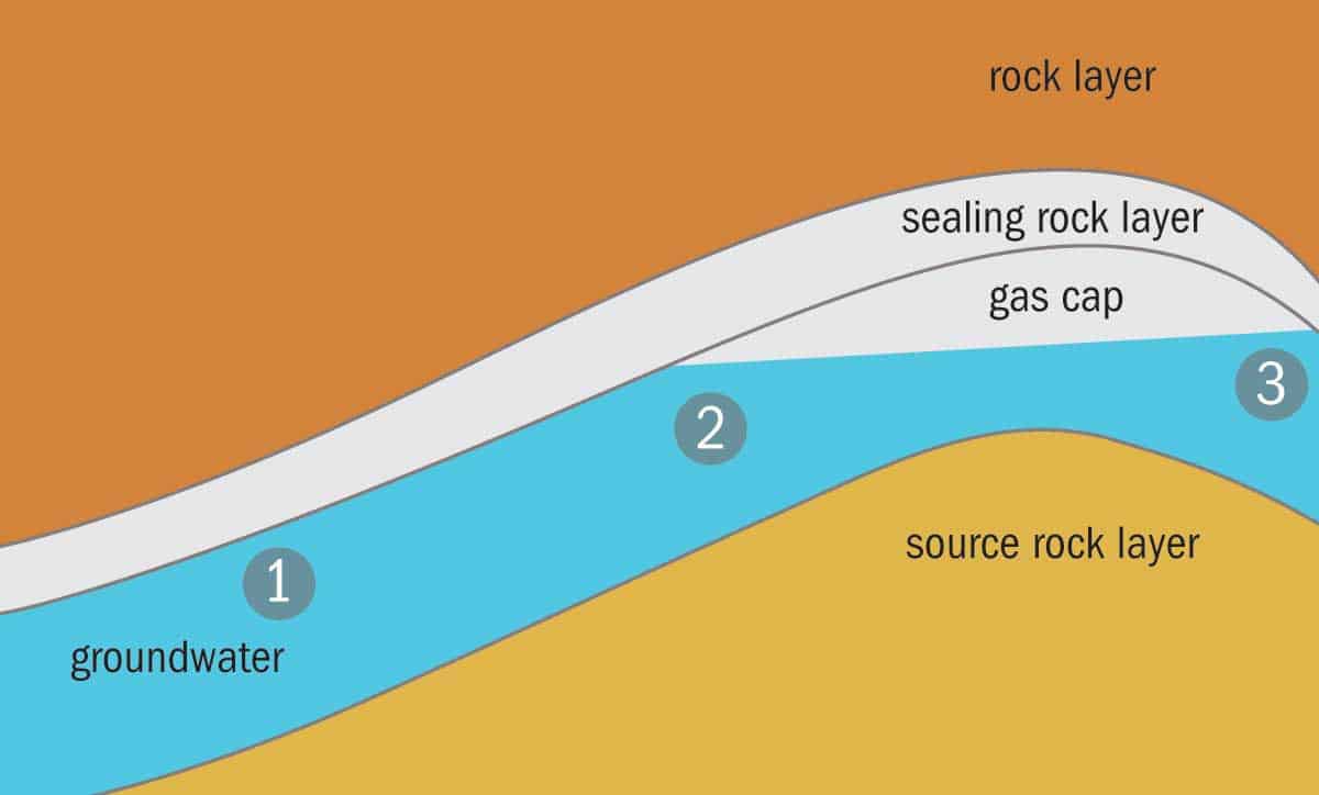
Helium migration: Once released from the source rock, helium and nitrogen can interact with groundwater (1), which carries the dissolved gases as it ascends. When the groundwater contacts a pre-existing gas cap containing methane or carbon dioxide (2), the nitrogen and helium partition out of the groundwater into the gas cap (3).
The primary migration process begins when particles in uranium and thorium-bearing minerals undergo radioactive decay, releasing alpha particles (helium-4 nuclei). The energy associated with this process produces “fission tracks” through the mineral, and helium atoms can readily diffuse along these tracks. While it is not yet known how efficient this escape process is, once helium has diffused out of the mineral it will accumulate in fluid inclusions and fractures within the source rock. For helium to then migrate out of the low-permeability source rocks into overlying layers, another input of energy is required. This typically comes in the form of heat and pressure from tectonic events such as rifting, mountain building or volcanic activity.
We do not fully understand the primary release process; however, we do know that the bulk migration of helium is enhanced by the presence of a carrier fluid or gas. In natural gas formations, high helium concentrations are always associated with high concentrations of nitrogen. The converse is not true, as many nitrogen-rich natural gas sources contain only trace amounts of helium; the explanation being that there are multiple sources of trapped nitrogen in the crust. Analyses have shown that radiogenic helium is consistently associated with nitrogen that has an isotope distribution characteristic of a source in the crystalline basement, indicating that the nitrogen is likely carrying helium out of source rocks.
Early in our research, we sampled well gases from existing helium-producing areas in the midwestern US and southern Canada. More recently, we worked with a helium exploration company, Helium One, to sample helium-rich gas seeps in the Tanzanian section of the East African Rift. All samples were rigorously analysed for information about the gas composition and the isotopic composition of the separated helium, other noble gases and nitrogen. This gave us an idea of the interaction between helium and its associated nitrogen carrier, and how they migrate out of source rocks. However, we still needed to account for the way in which helium and nitrogen moves (sometimes hundreds of kilometres) and collects into geological “traps” – a process known as secondary migration.
Our studies indicate that once helium and nitrogen are released from the source rock, they interact with groundwater in overlying strata (see figure above). Once enough helium and nitrogen are dissolved in the groundwater, they are able to form a separate nitrogen- and-helium-rich gas phase as the groundwater ascends to the surface and becomes depressurized. We think this is the mechanism for the near-pure nitrogen-helium gas fields found in North America.
Other helium-producing fields have a more complex makeup of gases. Some (such as LaBarge/Riley Ridge and Doe Canyon in the US) are known to contain primarily carbon dioxide, and others (like the North Dome in Qatar, Hassi R’Mel in Algeria and the Hugoton-Panhandle in the US) are rich in methane. The presence of significant concentrations of carbon dioxide or methane in these helium-rich natural-gas trapping structures gives us another clue as to the possible mechanisms behind helium trapping. If groundwater containing dissolved helium and nitrogen comes into contact with a pre-existing natural gas cap then helium and nitrogen will preferentially move from the groundwater into the gas cap.
But there is a complication. Because carbon dioxide and methane are both prevalent in the subsurface, there is a high risk that in locations where helium and nitrogen accumulate, the helium concentration may be diluted by large amounts of these other gases – potentially to levels that are not worth extracting commercially. In formations where we are relying on methane and carbon dioxide to strip dissolved helium and nitrogen, we need to establish a zone where the degree of dilution is “just right”. As an example, volcanic activity is a known source of high-carbon-dioxide gas fields. Therefore, in the right geological setting, the thermal aureole associated with magma emplacement may provide the heating needed to release helium from its source. However, if the trap is too close to the volcanic centre, the only gas you are likely to find there is carbon dioxide – whereas further from the volcanic source you are more likely to see nitrogen-rich helium gases like the ones that occur in the Tanzanian seeps we sampled.
Once helium has migrated into a gas-trapping structure, the preservation of helium in that trap depends on the rate at which helium is supplied to the deposit and the efficiency of the seal or trap to contain the gases. Trap destruction (caused by weathering, erosion or tectonic events) or a leaky seal (usually caused by the pressure in the reservoir exceeding the pressure in the overlying caprock) will result in helium being lost from the trap.
Next steps for helium exploration
Based on this preliminary helium exploration methodology, we have identified the Tanzanian region of the East African Rift as a potential helium-rich system. The region contains an ancient craton that has been perturbed by a much younger rifting event and, as a bonus, some of the gas seeps in the region are already known to be nitrogen-helium rich.
But our database and geochemical analyses of the helium-rich fields are lacking, especially when compared with the years of accumulated data for petroleum exploration. Continuing to sample and analyse natural helium occurrences so as to better understand and classify migration and accumulation processes is essential. Nevertheless, we believe we have taken an important step towards securing the future of our helium supply.
My physics degree at the University of Surrey, UK, included a “sandwich year” placement and one of the places I applied to was CERN. To maximize my chances of getting a job there, I wrote down whole areas that I would be interested in working in, including cryogenics. My interview with the cryogenics group at CERN didn’t go so well (I had actually forgotten what the word “cryogenics” meant), but somehow they offered me the placement anyway, and I loved it. I worked on the Large Hadron Collider magnets, looking at low-conductivity, high-strength materials such as carbon fibre and doing heat-transfer tests at cryogenic temperatures. By the end of the year I was hooked.
What did you do after you finished your undergraduate degree?
I did a PhD at the University of Southampton, UK, researching a type of cryocooler called a pulse tube refrigerator. Most commercial cryocoolers are of the Gifford–McMahon type, which use pistons to expand and contract gases; every time you expand the gas, it cools and you can, in effect, “store” the coolness in a particular area, which you then attach to whatever sample you want to cool down. The pulse tube is different in that it doesn’t have a physical piston moving, just a volume of gas, so there are fewer things that can break and less vibration because you don’t have mechanical things moving at high speeds. Pulse tube refrigerators are now a mature technology – you can buy them off the shelf – but at the time they were still very much in development.
What’s driving the adoption of technologies like that?
The great thing about coolers is that you can switch them on and leave them. You don’t have to continuously refill them with liquid helium and liquid nitrogen – you just press a button and as long as they’ve got electricity and water they keep on going for months, if not years. Another big driver is the cost of helium. Geoscientists have found more helium reserves, but they’re a long way from being brought online. That’s why everybody is turning towards cryogen-free cooling where they can. But liquid helium also has some big advantages. It’s got a lot of cooling power and it’s still relatively cheap to produce, even though the price has been going up. Plus, you need an awful lot of electricity to run cryocoolers. You need electricity to produce liquid helium too, but once it’s cold, it’s cold.
What are you working on now?
I work at ISIS, which is the UK neutron and muon source at the STFC’s Rutherford Appleton Laboratory. Our division provides support for the scientists and users coming to do experiments; we provide the equipment that gets very cold, very hot or reaches very high pressures. One system we’ve designed and built is a low-temperature stress rig – a sort of cold box that you can use to cool your sample, apply mechanical stress to it and then image it with neutrons. It has been used recently to do stress tests on high-temperature superconducting tape, which meant passing a current through the sample while cooling it and applying a tensile load, all while on a neutron beamline. In those circumstances, nothing is simple, not least because when you’re cooling things, they move and contract, and the properties of the material change. For example, many materials that are fine at room temperature become brittle once you cool them down.
Another system we’re working on is a low-temperature sample changer. Most of the time if you want to pull a low-temperature sample out of the neutron beam, you have to warm everything up, put your new sample in and then cool it back down again, which takes quite a long time. We’ve got a sample changer in production that works by attaching the sample to a little parachute, so that we can blow out the sample with helium, catch it with a robot arm, change it, drop in the new sample and let the gas out so that it sails down a tube where the temperature sensor makes an electrical connection at the base. At that point it gets cooled very quickly because it’s a small object and there’s minimal heat transfer. It’s similar to the sample changers used in some types of nuclear magnetic resonance machine. But there are lots of different technologies that have to work together: you’ve got the robots at one end, you’ve got the cryogenics, you’ve got the gas and the vacuum. As is often the case, cryogenics is only one part of a multidisciplinary system.
Aside from uncertainties in liquid-helium supplies, what are the other barriers to progress in cryogenics?
Here in Oxfordshire, we have a lot of cryogenics companies, and our biggest issue is the lack of skilled labour. Cryogenics is a specialized field and until recently you’ve not really been able to study it, either at school or at a technical college. We have helped to change that, and there’s now a university technical college down the road that will be training pupils up in cryogenics and vacuum use. There’s also a BTEC module (that is, a vocational qualification for 16-year-olds) in cryogenics and vacuum technology. We’re trying to make it part of the broader curriculum because cryogenics and vacuum are fundamental to so much of industry and technology. But even so, there’s a shortage of skilled labour. Cryogenics is very dependent on technical skills such as welding – you have to be able to build cryogenic vessels to certain safety standards.
The other issue I’d note is that most cryogenic companies are relatively small, and while they’re very good at what they do, they often don’t have the resources to expand. So if something new comes along, most of them won’t leap up and say “Right, okay, we’ll do that, we’ll develop it” because it’s too much of a risk for them. There’s just not the investment and the infrastructure here in the UK to support some of the big cryogenics projects coming up.
What would help with that?
It would help if there were funds available for riskier projects. Even in academic research, money is given for a specific project, and you cannot fail on that project, so you have to play it safe. And in industry, they can’t do basic development because they have to produce something and sell it – they can’t “play around” because they only get paid for what they deliver. I think that’s probably one thing that’s keeping cryogenic technology and superconductivity technology from growing as it should: industry can’t do development because they haven’t got money for it, and often academics can’t do it either because we’re not really here to develop things – yet if we don’t, industry can’t either. It’s especially hard in this economic climate, where there isn’t any spare money. Government officials like to put money in and get something out, just like in industry, but it’s quite hard when you’re developing technology because you don’t necessarily get the results as quickly as expected.
The British Cryogenics Council recently celebrated its 50th birthday. How has the field changed since it was founded?
Fifty years ago, the cryogenics industry was in its infancy. That’s not to say it was all about fundamental research, but superconductivity was still relatively new; the techniques of making superconductors work in practice were in the early stages; and cryogenics was very academically based. I think that’s been the biggest change. Cryogenics is an enabling technology now rather than a research area. Scientists are still using cryogenics because you can look at atoms and molecules more easily if you slow them down, but it’s also become an industrial tool, used in factories and MRI scanners as well as in particle accelerators.
What do you see as the major trends in cryogenics for the next 10 years?
There’s still a lot of development to be done on superconductivity, especially with high-temperature superconductors. At the moment, a lot of high-temperature superconducting materials are difficult to work with – you can’t roll them out into nice tapes like you can with low-temperature superconductors – so there’s more research needed to help them reach their potential. There are also some interesting “green” applications of cryogenics that may become more important. The so-called “hydrogen economy” has the potential to be huge for the cryogenics industry. If you’re going to run vehicles off hydrogen instead of fossil fuels, you’ll need a lot of hydrogen, and you’ll need to transport and store it somewhere either as a high-pressure gas or as a liquid, bearing in mind that hydrogen reacts with many metals causing embrittlement with long-term exposure. Then there’s the question of how you get the hydrogen into vehicles. If you have liquid-hydrogen filling stations, you’ll have to move liquid hydrogen from an underground tank up and into the vehicle while keeping it at a low temperature. All of that will involve cryogenic technology.
 By Matin Durrani